A cooling fan is easy to approve when all you ask is whether it spins.
That is also how expensive mistakes begin.
In industrial equipment, a fan can start normally, sound acceptable on the bench, and still fail once it is installed in the real enclosure. We see this often in electrical cabinets, telecom housings, automation assemblies, battery systems, and compact electronics. The fan is not being asked to move air through open space. It is being asked to work through filters, vents, wiring, heatsinks, internal partitions, and very limited installation geometry.
That is why I do not treat fan testing as a quick electrical check. A useful test has to answer a practical question: will this fan cool the actual equipment under real operating conditions, not just in a clean open-air setup.
Start With the Basic Electrical Check
The first step is still electrical. Before looking at airflow or noise, I want to know whether the fan is being tested under the right input conditions.
For an AC fan, that means confirming rated voltage and frequency. For a DC fan, it means confirming voltage, polarity, and any control signal requirements. I also check startup behavior. A fan that hesitates, starts inconsistently, or draws abnormal current at startup is already giving useful information.
Running current matters as well. If the measured current is clearly above expectation, the fan may be operating under stress even if it appears normal at a glance. In a short sample test, that may not look serious. In long-term service, it often is.
A fan does not have to fail dramatically to be wrong for the application. Sometimes it simply runs outside its intended condition and ages faster than it should.
Rotation Is Not the Same as Cooling
This is the point many buyers miss, especially during sample review.
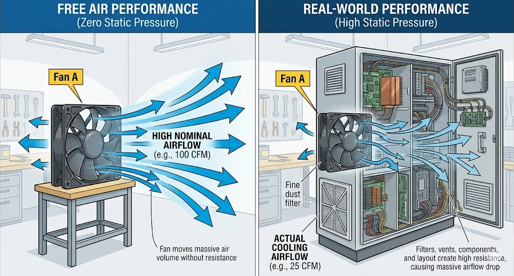
A fan that rotates is not necessarily delivering useful cooling. On the bench, airflow may look acceptable because there is little resistance and nothing inside the path to interfere with performance. Once that same fan is installed in equipment, the result can change completely.
In practice, I care less about whether air can be felt at the outlet and more about whether the fan is moving enough air to the place that actually needs protection. If the heat source sits behind a filter, a drive module, a dense wiring section, or a narrow internal channel, then the free-air impression tells very little.
That is why airflow testing should always be tied to the real thermal job. Otherwise the test confirms movement, not performance.
Static Pressure Changes Everything
Many cooling problems that look like airflow problems are really pressure problems.
A fan may be rated with enough nominal airflow on paper, but once it has to work through resistance, that number becomes much less useful. Filters, finger guards, louvers, heatsinks, ducts, cable bundles, and compact internal passages all create pressure loss. In some systems, that loss is the real reason overheating continues after a standard replacement.
When I test a fan for an application with any meaningful restriction, I want to know how the fan behaves under resistance, not only in free air. This is where the difference between fan platforms becomes important. An axial fan that works well in a more open enclosure may not be the right choice once the path becomes narrow or pressure-heavy. In those cases, a centrifugal blower may hold useful airflow more effectively.
A surprising number of fan failures are not electrical failures at all. They are selection failures caused by underestimating the system resistance.
Noise, Vibration, and Speed Stability
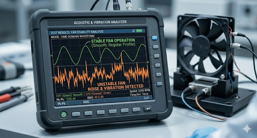
Noise is not only about comfort. In industrial equipment, it often tells you something about stability.
A fan that produces unusual vibration, inconsistent tone, or rough mechanical sound during operation deserves closer attention. The issue may come from imbalance, mounting mismatch, bearing stress, or the way the fan interacts with the enclosure. Even if the sound is still within an acceptable range, instability often shows up acoustically before it shows up as a clear failure.
I also pay attention to speed consistency. A fan that drifts, fluctuates, or behaves differently as temperature changes may still pass a short test and disappoint in the field. In control cabinets and telecom systems, where the equipment may run continuously, that kind of instability becomes a real service problem.
Short tests are useful. Stable tests are more useful.
Short Test vs Continuous Run
One of the simplest ways to misjudge a cooling fan is to stop the test too early.
A fan can look fine in the first ten minutes and behave very differently after several hours. This is especially true in compact industrial equipment, where internal heat builds gradually and the fan begins operating in a warmer, more stressful environment than it saw at startup.
For sample evaluation, I like to separate quick confirmation from run stability. The quick confirmation tells me whether the electrical behavior, startup, and obvious airflow direction are correct. The longer run tells me whether temperature rise, current behavior, mechanical sound, and cooling performance remain stable over time.
This does not always require a sophisticated lab to be useful. Even a practical extended run in the intended enclosure reveals much more than an open-air spin check on a bench.
Bench Testing and Installed Testing Are Not the Same Thing
This is probably the most important distinction in the whole process.
Bench testing is useful for confirming basic operation. It tells you whether the fan starts correctly, whether the input is appropriate, whether the current looks reasonable, and whether the fan behaves normally in a simple environment.
Installed testing tells you whether the cooling solution actually works.
Once the fan is mounted in the equipment, the system begins to show its real character. Internal resistance, recirculation, blocked discharge, poor intake location, and uneven thermal layout all begin to matter. A fan that looked perfectly acceptable on the bench may suddenly show weak airflow at the hotspot or unstable temperature behavior under sustained load.
That is why I never treat free-air testing as final approval for an OEM project. It is only the first layer.
| Test Condition | What It Tells You |
|---|---|
| Free-air test | Basic operation and nominal behavior |
| Bench electrical test | Voltage, current, startup, polarity or frequency match |
| Installed system test | Real airflow inside the enclosure |
| Continuous run test | Stability over time, temperature rise, and mechanical consistency |
What I Look for Before Approving a Fan Sample
When a customer sends us an application or when we prepare samples for an OEM project, I try to keep the approval standard practical.
First, the voltage and frequency have to match the system. That sounds obvious, but it is still one of the easiest mistakes to make, especially in export equipment and replacement-driven projects.
Second, the fan has to suit the airflow path, not just the opening size. If the enclosure has restriction, then pressure capability matters. If the layout is compact, then airflow direction may matter more than raw volume.
Third, the integration details have to work. Connector type, cable length, mounting structure, control signal, and protection level all affect whether the fan is truly suitable for production.
Fourth, the sample has to remain stable during operation. I want to see predictable current draw, acceptable noise behavior, and no sign that the fan is struggling once the enclosure warms up.
A fan sample is not approved because it is close enough. It is approved because it behaves correctly in the system it is meant to protect.
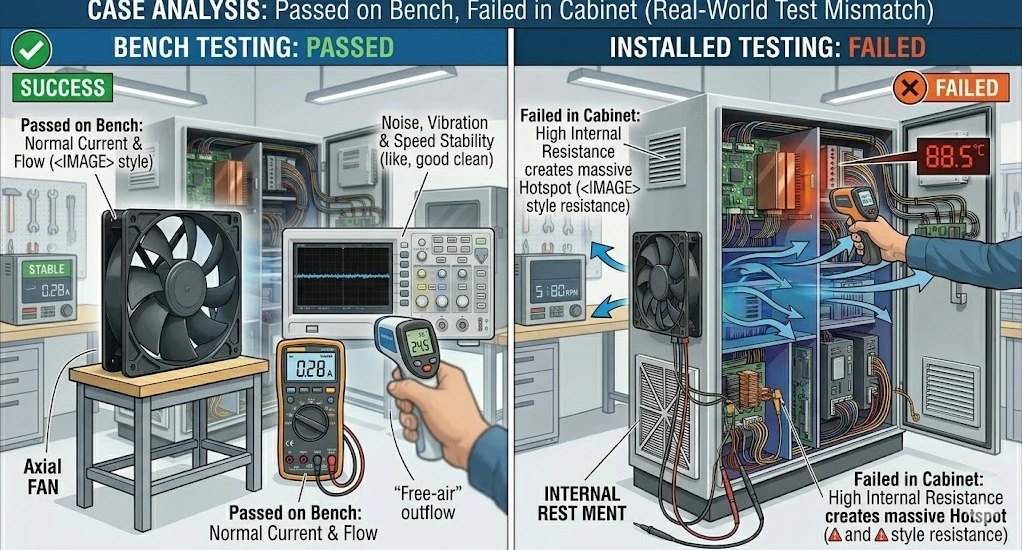
Case Analysis: Passed on the Bench, Failed in the Cabinet
A control cabinet project we reviewed not long ago is a good example of why this matters.
The cabinet contained a PLC, a drive, and several power modules. The original sample fan passed its initial bench test without trouble. Startup was clean, voltage was correct, current looked normal, and the airflow felt acceptable in open air. If the test had ended there, the sample likely would have been approved.
Once the fan was installed in the cabinet, the result changed. Air had to enter through a filter, pass a crowded internal section, and reach the drive area where the thermal load was concentrated. Under continuous operation, temperature alarms began appearing around the drive module even though the fan was still running normally.
The problem was not that the sample was defective. The problem was that the test had confirmed basic operation but not real installed performance. The axial fan simply was not maintaining enough useful airflow through the resistance path inside the enclosure.
The final solution moved to a higher-static-pressure centrifugal blower with adjusted mounting and cable configuration. After that change, airflow through the restricted section improved and the hotspot around the drive area dropped to a stable level.
That project is exactly why I prefer enclosure testing over assumptions drawn from open-air behavior.
How We Approach Fan Testing at FanACDC
From a manufacturer’s perspective, fan testing is not only about quality control at the component level. It is also about selection confidence.
We test for electrical behavior, airflow, noise, and consistency, but for OEM projects the more important part is matching the fan to the actual use case. That may involve AC, DC, EC, axial, or centrifugal platforms depending on the airflow path and resistance involved. In some projects the right answer is a standard model. In others it is a modified configuration with different voltage, connector, cable, bearing option, or protection level.
The point is to reduce mismatch before production. It is much easier to adjust the cooling strategy during sample review than after the enclosure is already in service.
FAQ
How do you test if a cooling fan is working properly?
Start with the electrical basics: voltage, frequency or polarity, startup behavior, and running current. Then check airflow, noise, vibration, and performance in the actual installed system, not only in free air.
What should be checked before approving a cooling fan sample?
Voltage compatibility, airflow fit, static pressure suitability, connector and cable details, mounting compatibility, noise behavior, and stability during continuous operation.
Is airflow more important than fan size?
In most industrial applications, yes. Fan size matters, but useful airflow inside the real enclosure matters more than frame dimensions alone.
How do you test a cooling fan under static pressure?
The fan has to be evaluated in a setup that reflects the actual restriction of the application, such as filters, ducts, heatsinks, or narrow internal channels. Free-air testing alone will not show pressure-related losses.
Why can a fan pass bench testing but fail in the equipment?
Because the installed system introduces resistance, heat concentration, and airflow limitations that do not appear in a simple open-air test. The fan may be healthy but still mismatched to the enclosure.
Conclusion
A cooling fan should not be approved simply because it starts, spins, and moves some air on the bench. For industrial equipment, that standard is too low.
Real testing means checking electrical fit, airflow behavior, pressure performance, mechanical stability, and enclosure-level cooling under practical operating conditions. The more compact or resistance-heavy the system becomes, the more important that full view becomes.
From where I sit as a manufacturer, the best fan test is the one that answers the real application question early enough to prevent trouble later. If the enclosure is difficult, the airflow path is restricted, or the sample result feels only partially convincing, that is usually the right moment to look beyond a standard part and test the cooling solution more seriously.