
Fan speed and airflow are closely related, but they are not interchangeable specifications. RPM tells you how fast the impeller turns. CFM or m³/h tells you how much air moves. Once the fan is installed behind a filter, grille, heat sink, or duct, static pressure decides how much of that airflow the system actually receives.
That distinction matters when you are comparing cooling fans. A faster fan may deliver more air, but it can also create more noise and draw much more power. It may still fail to cool a cabinet if the airflow path is badly restricted.
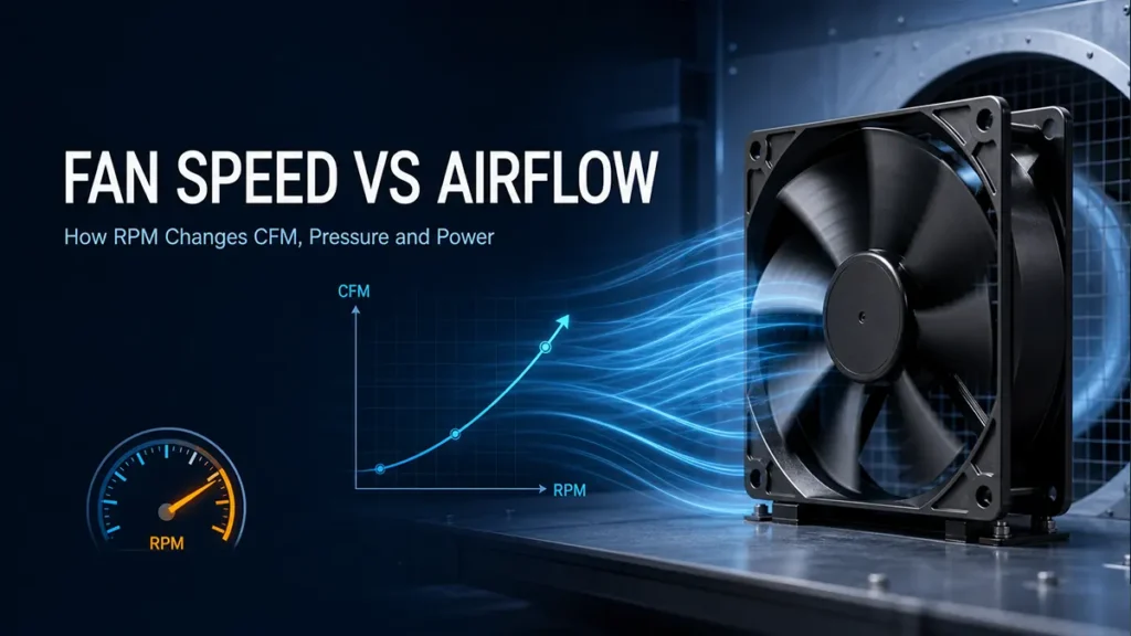
This guide explains fan speed vs airflow using the fan laws, a worked RPM example, fan curves, system resistance, and practical speed-control choices for industrial equipment.
Quick Answer: Does Higher Fan Speed Increase Airflow?
Yes. For the same fan in the same system, airflow changes approximately in direct proportion to rotational speed. If speed increases by 10%, airflow is expected to increase by about 10%. Pressure changes by the square of the speed ratio, and power changes by approximately the cube.
Airflow ratio = New RPM ÷ Original RPM
These are fan affinity laws, not a promise that any two different fans with the same RPM will produce the same CFM. Blade diameter, pitch, motor, frame, and pressure capability all change performance. The equations also assume the same fan geometry, similar air density, and an unchanged system resistance curve.
Fan Speed and Airflow Are Different Measurements
What Fan Speed Means
Fan speed is normally stated in revolutions per minute, or RPM. It is useful for control, alarm monitoring, and comparing operating modes of the same fan. RPM by itself does not tell you the delivered airflow.
What Airflow Means
Airflow is a volume flow rate, commonly shown as CFM, m³/h, m³/min, or L/s. A catalog’s maximum airflow is usually measured with very little external restriction. An installed fan normally delivers less because the equipment creates pressure loss.
Why Static Pressure Connects the Two
Static pressure is the fan’s ability to overcome resistance. A dense filter or narrow air path needs more pressure than an open enclosure. The fan’s actual airflow appears where the fan curve intersects the system resistance curve. The guide to static pressure vs airflow explains why maximum CFM and maximum static pressure are endpoint ratings, not normal operating conditions.
The Three Fan Laws
The fan laws are the fastest way to estimate how changing the speed of the same fan affects airflow, pressure, and power. Use N for rotational speed, Q for airflow, P for pressure, and W for power.
1. Airflow Changes with Fan Speed
Q2 ÷ Q1 = N2 ÷ N1
If speed falls from 2,000 RPM to 1,600 RPM, the speed ratio is 0.8. Estimated airflow also falls to 80% of the original value.
2. Pressure Changes with the Square of Fan Speed
P2 ÷ P1 = (N2 ÷ N1)^2
At 80% speed, estimated pressure capability becomes 0.8², or 64% of the original. This is why a slower fan can lose the ability to push air through a restrictive filter even when the free-air CFM still looks acceptable.
3. Power Changes with the Cube of Fan Speed
W2 ÷ W1 = (N2 ÷ N1)^3
At 80% speed, ideal fan power becomes 0.8³, or about 51% of the original. Real electrical input includes motor and controller losses, so measured savings may differ, especially at very low speed. Still, the cube relationship shows why variable-speed control is valuable when full airflow is not needed.
Fan Speed vs Airflow Example
Assume a fan produces 1,000 CFM at 2,000 RPM, 200 Pa, and 100 W at a particular operating condition. The ideal fan-law estimates are:
| Speed | RPM | Estimated airflow | Estimated pressure | Estimated fan power |
| 100% | 2,000 | 1,000 CFM | 200 Pa | 100 W |
| 90% | 1,800 | 900 CFM | 162 Pa | 72.9 W |
| 80% | 1,600 | 800 CFM | 128 Pa | 51.2 W |
| 70% | 1,400 | 700 CFM | 98 Pa | 34.3 W |
These values are an idealized teaching example, not product data. They assume the same fan, unchanged system curve, and similar air density. A real fan datasheet or test should be used for final design.
The key point is that airflow falls in a straight-line relationship with speed, but pressure and power change much faster. Reducing speed by 20% does not mean reducing pressure and power by only 20%.
Why Installed Airflow Does Not Depend on RPM Alone
The Fan Has a Performance Curve
A fan curve plots airflow against static pressure at a stated speed. At low pressure, the fan can move more air. As resistance increases, airflow normally falls. Different fan designs can have very different curves even when their maximum RPM is similar.
The Equipment Has a System Curve
The enclosure, duct, filter, heat sink, and openings create a system resistance curve. For many turbulent airflow systems, pressure loss rises roughly with the square of airflow. Doubling airflow can therefore require about four times as much pressure from the fan.
The Intersection Is the Operating Point
The operating point is where the fan curve and system curve meet. Increasing RPM shifts the fan curve upward and to the right, creating a new intersection with higher airflow and pressure. The amount of airflow gained depends on the whole curve, not RPM alone.
Restrictions Can Consume the Extra Pressure
If a filter is dirty or the vent area is too small, the extra pressure from higher speed may be spent overcoming restriction. You may see a large increase in noise and power but only a modest drop in component temperature. Fixing the airflow path can be more effective than using a faster fan.
How Fan Speed Moves the Fan Curve
Imagine one fan running at 70%, 85%, and 100% speed. Each speed has its own airflow-pressure curve. At 100% speed, the curve reaches farther toward both maximum airflow and maximum pressure. At 70% speed, the curve is lower, and its intersection with the same system curve moves to a lower operating airflow.
This makes a family of speed curves useful for thermal control. Instead of switching an oversized fan fully on and off, a controller can choose the lowest speed that keeps the equipment below its temperature limit. The result is often lower average power and less noise.
Fan Speed Control Methods
PWM Control for DC Fans
Many brushless DC fans accept a dedicated PWM control signal. The fan continues to receive its rated supply voltage while the control input commands speed. Use the specified PWM frequency, logic level, duty-cycle range, and wiring. Do not assume every two-wire DC fan accepts PWM on its power lead.
DC Voltage Control
Some DC fans allow speed adjustment by changing supply voltage within an approved range. The fan must still start reliably at the lowest voltage and under the worst temperature and pressure condition. A dedicated PWM model usually offers a wider and more predictable control range.
EC Fan Control
EC fans combine an electronically commutated motor with integrated drive electronics. Depending on the model, speed may be controlled by PWM, 0–10 V, or another signal. This makes EC technology useful where the equipment has AC input but needs efficient variable-speed operation.
AC Fan Speed Control
Speed control for an AC fan depends on motor design. Approved methods may include transformer steps, phase control, or frequency control. An arbitrary voltage controller can cause poor starting, extra heat, vibration, or motor damage. Follow the fan manufacturer’s approved control method.
Fan Speed, Noise, and Energy Use
Higher Speed Usually Means More Noise
Aerodynamic noise rises quickly with speed, and tonal motor noise may also become more noticeable. A larger fan running more slowly can sometimes meet the same airflow target with less noise than a smaller high-speed fan, but the comparison must be made at the same pressure.
Lower Speed Can Save Substantial Power
The cube relationship makes speed control attractive in variable thermal loads. A fan that spends most of its time near 70–80% speed can use much less energy than a fan held at full speed. The actual electrical saving should be checked on the fan’s input-power curve or by measurement.
Cooling Margin Still Comes First
Reducing speed is only useful if every critical component stays within its temperature limit. Test at maximum ambient temperature, highest equipment load, lowest supply tolerance, and the expected end-of-service filter condition.
When Increasing Fan Speed Does Not Fix Cooling
- Hot exhaust air recirculates back into the intake.
- The inlet or outlet opening has too little free area.
- A filter, grille, or heat exchanger creates more pressure drop than the fan can overcome.
- Cables or components block the flow immediately in front of the fan.
- Air bypasses the hot components instead of passing through them.
- The enclosure has no balanced path for make-up air or exhaust.
- The fan is rotating in the wrong direction or installed with the wrong airflow orientation.
Before selecting a faster model, inspect the flow path, measure inlet temperature and key component temperatures, and compare the current operating point with the fan curve. A small duct or baffle change can sometimes outperform a large RPM increase.
How to Choose the Right Speed and Airflow
1. Define the Thermal Requirement
List heat load, maximum ambient temperature, allowed internal temperature rise, and the temperature limits of critical components. Calculate a starting airflow target, then plan to validate it in a prototype.
2. Estimate System Resistance
Include filters, grilles, vents, heat exchangers, ducts, and internal obstructions. If pressure-loss data is unavailable, measure a prototype or use a conservative estimate and test more than one fan.
3. Compare Fan Curves at the Required Voltage
Look for the airflow where the fan curve crosses the estimated system curve. Confirm that speed, power, noise, and current are acceptable at that point. Free-air CFM is only a screening value.
4. Add a Defined Margin
Allow for filter loading, supply tolerance, altitude, temperature, aging, and production variation. Avoid an undefined margin that simply pushes the fan to maximum speed.
5. Validate and Tune the Control Curve
Run the complete equipment at worst-case load. Check temperatures in steady state and during transients. Then set the minimum and maximum fan speeds, alarm thresholds, and temperature-control curve.
Common Fan Speed vs Airflow Mistakes
- Comparing RPM between two different fan sizes as if RPM were an airflow rating.
- Using maximum CFM as the installed airflow behind a filter or heat sink.
- Applying the fan laws across unrelated fan geometries or different air densities.
- Assuming a 20% speed reduction causes only a 20% change in pressure and power.
- Ignoring minimum starting speed, startup current, and controller compatibility.
- Increasing speed before correcting recirculation or a restricted air path.
- Choosing a fan from sound level alone without checking pressure at the required airflow.
Conclusion
Fan speed vs airflow is easiest to understand through three relationships: airflow follows speed, pressure follows the square of speed, and fan power follows approximately the cube. Those rules are useful for estimation, but the installed operating point still comes from the fan curve and system curve.
For an industrial cooling project, compare fans at the airflow and pressure your equipment actually needs. LINKWELL supplies AC fans, DC fans, EC fans, and centrifugal fans. Share your voltage, available space, target airflow, pressure estimate, temperature range, noise limit, and control method to narrow the selection efficiently.
Fan Speed vs Airflow FAQ
Is airflow directly proportional to fan speed?
Approximately, yes, for the same fan in the same system under similar air conditions. If RPM changes by 10%, airflow is expected to change by about 10%. Use the actual fan curves for final selection.
Does doubling fan speed double airflow?
The ideal fan laws predict twice the airflow, four times the pressure, and eight times the fan power. In practice, the fan and motor may not be capable of doubling speed, and noise, stress, power, and system behavior may make the result unsafe or impractical.
Does higher RPM always mean better cooling?
No. Cooling depends on delivered airflow through the hot components, inlet air temperature, heat-transfer area, and system resistance. Higher RPM may add noise and power without fixing recirculation or bypass airflow.
Why does airflow drop after a fan is installed?
The enclosure adds resistance. Filters, guards, vents, heat sinks, ducts, and component layout require static pressure, so the fan moves from its free-air endpoint to an installed operating point with lower airflow.
Does reducing fan speed save power?
Usually. The ideal fan laws predict power in proportion to the cube of speed, so a modest speed reduction can create a large saving. Motor and controller losses mean actual electrical input will not follow the cube law perfectly.
How does PWM affect airflow?
PWM changes the commanded speed of a compatible fan. Airflow generally tracks the resulting RPM, not the duty-cycle number by itself. Use the model’s PWM-to-RPM curve because minimum duty, control frequency, and response vary by fan.
Can two fans increase airflow?
Two identical fans in parallel can increase airflow, while two in series can increase pressure. The real gain is normally less than the theoretical value because the system curve and fan interaction change. Use combined performance curves and allow spacing to reduce interference.
Should I select a fan by RPM or CFM?
Select by the required airflow and static pressure first. Then check RPM, power, noise, voltage, life, size, protection, and control features. RPM is useful information, but it is not a substitute for a fan curve.

