
Installing two fans does not automatically make a cooling system redundant. If both fans share one connector, one controller, one blocked filter or one narrow airflow path, a single fault can still remove most of the cooling.
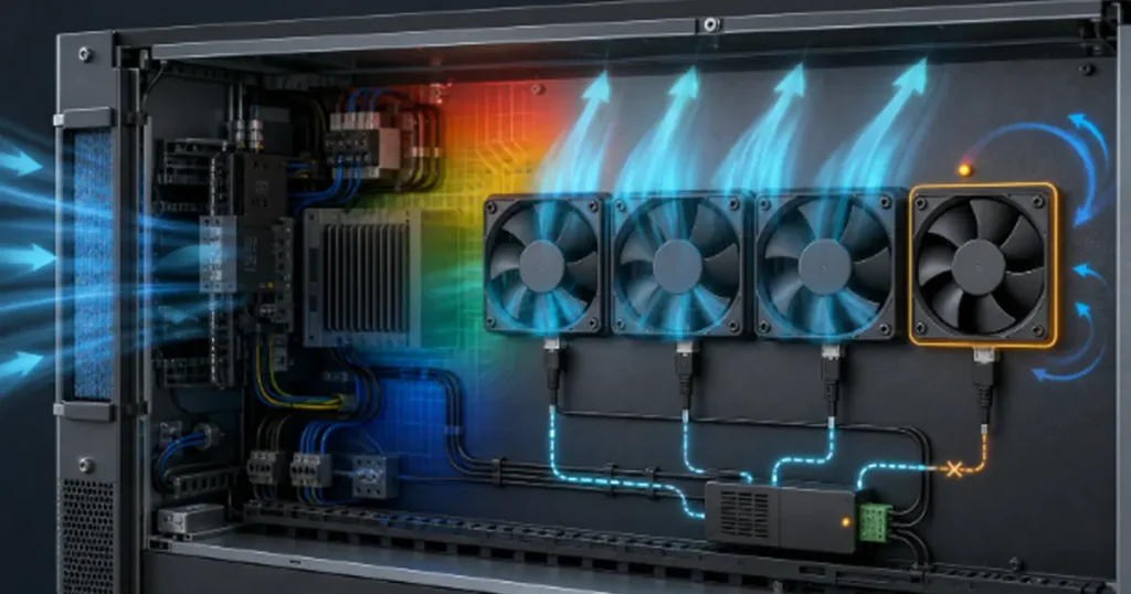
Fan redundancy means the equipment can meet a defined safe thermal duty after a specified fan-related failure. That definition needs an airflow target, an operating time and a response: continue at full load, derate, alarm for service, or shut down safely.
What fan redundancy must prove
A redundant cooling design starts with a precise fault statement. Saying only that one fan fails is not enough. The test may need to represent loss of rotation, a seized rotor, an open winding, a shorted power lead, loss of the control signal, loss of a shared power rail or removal of a hot-swap module. Each fault changes the airflow path differently.
Next define the safe state. Full rated output and a controlled derated mode may require different airflow targets and allowable operating times. Those values must come from the thermal limits and validation plan for the actual equipment, not from a generic N+1 rule. A short service window may be acceptable in attended equipment but unsuitable for a remote installation.
| Redundancy claim | Evidence you need |
|---|---|
| One fan can fail without shutdown | Temperatures remain within defined limits after the worst credible single-fan fault |
| Full load is maintained | Degraded fan array still meets required airflow and pressure at full heat load |
| Hot-swappable | Electrical safety, connector sequencing, airflow during removal and replacement time are validated |
| Failure is detected | Fault monitor identifies stall or loss of performance within a stated time without nuisance alarms |
| No single point of failure | Power, control, sensing and airflow-path faults have been reviewed, not only the fan motors |
Redundancy belongs to the complete cooling system and its controls. The fan count on the bill of materials does not prove it.
N, N+1, N+2 and 2N cooling
N is the minimum number of operating cooling units required to meet the defined duty. If three fans are needed, N = 3. An N+1 system installs one additional unit so the duty can still be met after one unit is unavailable. N+2 allows two units to be unavailable under the stated conditions.
2N means two complete sets, each capable of carrying the full duty. For true 2N behavior, the sets need sufficient independence. Two fan banks on the same power supply, control board and filter are not two independent cooling trains.
| Architecture | Installed capacity | Typical use | Main trade-off |
|---|---|---|---|
| N | Only the required capacity | Noncritical equipment with acceptable shutdown | A fan outage reduces cooling below design duty |
| N+1 | One extra unit | UPS, telecom, servers, chargers and industrial controls | Remaining units and airflow path must handle one-unit-out duty |
| N+2 | Two extra units | Long service intervals or multiple-maintenance risk | More space, power, controls and cost |
| 2N | Two complete duty sets | Very high availability or separated cooling trains | Largest footprint and common-cause separation challenge |
The U.S. Department of Energy’s fan-system sourcebook notes that parallel fan arrangements can provide redundancy and allow maintenance without stopping the entire process. It also cautions, in effect, that total output falls when one unit fails unless the remaining capacity is sufficient. That last condition is what distinguishes a spare fan from a redundant system.
Active-active vs duty-standby fans
In an active-active design, all installed fans run during normal operation. With N+1 capacity, they can share the load below maximum speed. If one fails, the remaining fans ramp up. Lower normal speeds can reduce sound and input power when the system has enough reserve, but the degraded condition still needs stable control and sufficient pressure margin.
In a duty-standby design, the N duty fans run while the spare is stopped. On a fault, the controller starts the standby fan. The spare avoids normal running hours, but a dormant fan can still fail to start because of contamination, connector problems, bearing condition or control faults. Periodic exercise and proof-of-start logic are important.
Rotating duty assignments can equalize operating hours. It can also expose a latent problem earlier, which is useful, but the changeover itself becomes a control event that should be tested. Avoid rapid switching that creates temperature or pressure oscillation.
| Question | Active-active | Duty-standby |
|---|---|---|
| Are all fans proven during normal operation? | Yes | Only if standby is exercised |
| Failure response | Remaining fans increase speed | Standby starts, sometimes with duty fans changing speed |
| Normal operating speed | Often lower | Duty fans may run faster |
| Stopped-fan backflow risk | Appears mainly after a fault | Present during normal operation unless isolated |
| Control complexity | Load sharing and ramp control | Start proof, exercise cycle and changeover logic |
Neither strategy is universally more reliable. Choose based on the fault modes, maintenance model, acoustic limits and how the array behaves with a nonrunning fan.
Size the system at the degraded operating point
You cannot estimate one-fan-out airflow by dividing the normal total by the number of fans. Parallel fan curves combine horizontally at a common pressure, while the system resistance rises roughly with airflow squared in many turbulent systems. When one fan stops, the operating point moves on both the array curve and the system curve.
Use the same method described in fans in parallel vs series: build the array curve at the relevant speed, then intersect it with the complete system curve. Repeat with one fan removed from the active curve and include the stopped fan’s leakage or obstruction path.
For active-active N+1, check whether the remaining fans can ramp fast enough and whether their motors, drives, connectors and power supply can carry the higher current continuously. A control design that allows 100% command does not prove the fans have enough pressure margin at that speed.
For duty-standby, include start time and thermal inertia. The equipment temperature continues to rise between fault onset, detection, standby start and restored airflow. A large heat sink may provide useful ride-through; a small power module with high heat flux may not.
Record two duty points: normal operation and the worst-case one-fan-out condition. For each point, document fan speed, airflow, pressure, input power and the temperatures of critical components.
Use loaded-filter resistance and high ambient conditions in the degraded case. A system that passes with a clean filter at room temperature may have no redundancy near the end of the maintenance interval.
A stopped fan can become an airflow leak
A stopped fan is an opening through the pressure boundary. In a parallel array, air from the active fans may flow backward through it instead of crossing the heat exchanger or cooling the equipment. A freely windmilling rotor may leak differently from a seized rotor, and removal of a fan module can create a larger opening than either.
Isolation dampers, shutters or check devices can reduce backflow, but they add pressure loss and may stick. Their opening pressure must work at normal low-speed operation, and their failure position belongs in the FMEA. A damper that proves redundancy at full speed may flutter or remain partly closed during quiet mode.
Physical partitions can keep one fan’s discharge from feeding another inlet. Plenum geometry and sealing around each frame also matter. If all fans discharge into one unrestricted space, map the pressure zones rather than assuming equal sharing.
Test at least these states:
- failed fan electrically off but free to rotate;
- rotor mechanically blocked;
- fan module removed, if field removal is allowed;
- isolation device stuck open;
- isolation device stuck closed on a healthy fan;
- one fan running at the wrong direction or speed after service.
Measure net airflow through the intended cooling path, not merely the speed of the surviving fans. A controller can report healthy RPM while much of their output recirculates through the failed position.
Remove common electrical and control failures
Separate fan motors do not help if a single fuse, connector, harness or controller disables all of them. Trace the power path from source to each fan and mark every shared element. Decide which shared faults are acceptable and which require separation.
Practical separation may include independent current protection, separate connectors, isolated control outputs and routing that prevents one damaged cable from affecting the bank. For 2N claims, review upstream supplies and protective earth as part of the equipment safety architecture rather than making informal wiring changes.
Control signals can create hidden common causes. Depending on the input circuit and fault behavior, one shorted 0-10 V or PWM control line may disturb every fan that shares the signal. Confirm fault containment, input impedance and what each fan does when the command is open, shorted or out of range.
Firmware is another common point. A single temperature sensor, corrupted setpoint or stalled communication task can leave all fan channels at the wrong speed. Independent overtemperature protection or a hardware-safe fallback may be justified in high-risk equipment.
| Shared element | Failure question | Possible design response |
|---|---|---|
| Power supply | Can one supply fault stop all fans? | Separate rails, backup supply or defined passive/derated safe state |
| Fuse or connector | Does one open connection remove the full bank? | Per-channel protection and connectors |
| Control command | What happens on open or short circuit? | Safe default speed, independent channels or validated fault logic |
| Temperature sensor | Can one bad reading command insufficient cooling? | Plausibility checks, redundant sensing or hard overtemperature trip |
| Filter or inlet | Can one blockage starve every fan? | Maintenance monitoring, divided paths or sufficient dirty-filter margin |
Detect the failure and respond in time
A tachometer or FG output confirms rotation, not airflow. A fan can rotate with a blocked inlet, broken blade, reversed installation or severe recirculation. Combine speed feedback with temperature sensing and, where the risk justifies it, pressure or airflow monitoring.
RD or alarm outputs can indicate a stall according to the fan’s internal logic. Confirm the threshold, delay, output type and startup behavior. The fan sensor guide explains the difference between speed feedback and alarm functions; they should not be treated as interchangeable contacts.
Set detection delays long enough to ignore normal acceleration but short enough to preserve thermal ride-through. After detection, the controller may ramp surviving fans, start a standby, derate the heat source, raise a remote alarm or shut down. The order and timing should be explicit.
Design the alarm for maintenance, not just firmware logs. Identify the failed position, record the time and operating conditions, and make the replacement procedure clear. If the equipment continues running, define how long it may remain in the nonredundant state.
The controller must determine whether cooling performance has fallen, choose the response that restores a safe state and report clearly that the system has lost spare capacity.
A periodic self-test can detect a standby fan that no longer starts. Run it under conditions that will not create unsafe pressure transients, and verify actual speed feedback rather than assuming a command was executed.
Fan redundancy validation test plan
Start with a production-intent prototype at maximum expected heat load. Use the normal and worst-case ambient conditions, the minimum allowed supply voltage and the filter condition that represents the maintenance limit. Instrument critical components, inlet air, outlet air, fan speed and electrical input.
- Establish steady normal operation and record the baseline duty point.
- Fail one fan using the defined electrical fault and record detection time, control response and temperature rise.
- Repeat with a mechanically blocked fan to capture backflow and obstruction effects.
- If hot swap is claimed, remove the module using the approved procedure and measure the entire service interval.
- Fail shared control signals, sensors and individual protective devices according to the FMEA.
- Confirm derating, alarm and shutdown thresholds in the correct order.
- Restore the system and verify that alarms clear correctly without hiding an intermittent fault.
Do not stop the test when the controller reports success. Continue until temperatures stabilize or the defined ride-through period ends. Inspect local hotspots; average outlet temperature can conceal one component that lost its airflow zone.
Repeat important tests at low load or quiet mode. Isolation shutters and parallel fan controls sometimes behave worse at low pressure than at the full-load condition used for qualification.
Record acceptance limits before testing. Useful limits include maximum component temperature, minimum net airflow or pressure, maximum response time, allowable acoustic level in degraded mode and maximum continuous duration before service.
Finally, run an endurance or cycling test appropriate to the application. Redundancy adds connectors, dampers and changeover events that can fail even if the individual fans have strong life data.
What to specify when buying redundant cooling fans
Provide the normal and one-fan-out airflow-pressure duty points. State whether the array is active-active or duty-standby, the number of fans, the required speed reserve and the expected dirty-filter resistance. Include the plenum layout so the supplier can see possible recirculation paths.
For each fan, specify voltage range, maximum allowable current, control input, speed-feedback or alarm output, connector and cable requirements, operating temperature, ingress protection, bearing orientation, life target and applicable approvals. If fans share a control signal, disclose the circuit and ask for written compatibility confirmation.
Request fan curves or tested array data at both normal and degraded speeds. Ask which test method was used and whether the reported curve represents the complete array rather than one fan multiplied by quantity. Final equipment testing remains essential because the actual plenum, grille, filter and electronics are part of the airflow system.
Ask for fault behavior: what happens on loss of control, blocked rotor, overtemperature, undervoltage and feedback-wire faults? Confirm whether alarm outputs are open collector, pulse, relay or another interface and whether they are fail-safe for wire breaks.
LINKWELL can review an OEM fan-redundancy requirement when you provide the two duty points, mechanical layout and control interface. The fan model is only one part of the recommendation; degraded airflow and fault response must be designed at equipment level.
FAQ
What is N+1 fan redundancy?
N is the number of fans required to meet the defined cooling duty. N+1 installs one additional fan so the system can meet that duty after one fan becomes unavailable.
Are two fans always redundant?
No. If both are required at full speed, the design is N, not N+1. Shared power, control, sensing or airflow-path faults can also defeat redundancy.
Should redundant fans run at the same time?
They can. Active-active designs share the load and ramp surviving fans after a failure. Duty-standby designs keep a spare stopped. Both approaches need failure-mode and thermal validation.
How much airflow remains when one parallel fan fails?
It is not a simple fraction. Combine the surviving fan curves at a common pressure, include leakage through the stopped position, and find the new intersection with the system curve.
Is tachometer feedback enough to prove redundant cooling?
No. Tachometer feedback proves rotation. Add temperature monitoring and, where required by risk, pressure or airflow sensing to detect blocked paths and recirculation.
Do stopped fans need isolation dampers?
Not always, but you must evaluate reverse flow through the stopped fan. Dampers or shutters can help and can also add loss or fail, so test both their normal and fault positions.
What is the difference between N+1 and 2N cooling?
N+1 adds one unit beyond the minimum requirement. 2N provides two complete duty-capable sets and generally requires stronger separation from common power, control and airflow failures.

