
Two fans can carry the same model number, run from the same supply and still settle at slightly different speeds. That does not automatically mean one is defective. Rated speed is normally a nominal or controlled value measured under stated conditions, while real production units operate within a permitted range.
The useful engineering question is not simply, “Are the RPM readings identical?” It is whether the measured variation is inside the model specification and whether the resulting airflow still protects the equipment at its worst thermal condition.
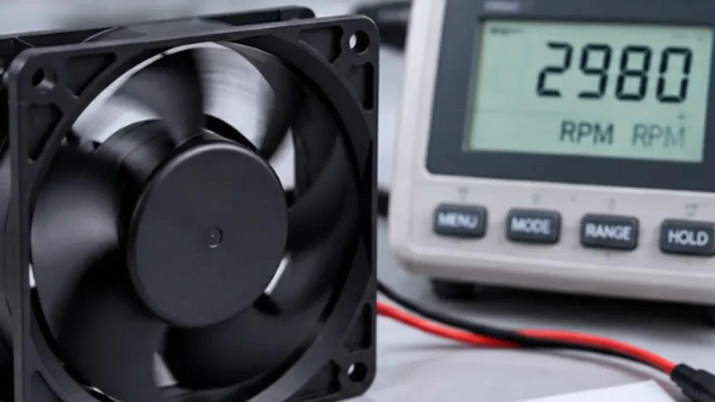
What Does Cooling Fan Speed Tolerance Mean?
Cooling fan speed tolerance describes the acceptable difference between a fan’s measured rotational speed and its stated speed under defined test conditions. A datasheet may express it as a percentage, an RPM band, or minimum, typical and maximum values. These formats are not interchangeable unless the test voltage, temperature, back pressure and control input are also the same.
For example, if a model is specified at a nominal speed of 3,000 RPM with a tolerance of plus or minus 10 percent, the simple acceptance band would be 2,700 to 3,300 RPM under the stated conditions. This is only an illustration. It must not be applied to a LINKWELL fan unless that exact tolerance appears in the approved datasheet.
Note: A rated RPM without a tolerance and test condition is not a complete acceptance specification. Ask for the model-specific limit before using RPM as an incoming-inspection criterion.
Nominal Speed, Minimum Speed and Speed Stability Are Different
| Term | What it tells you | What it does not tell you |
|---|---|---|
| Nominal or rated speed | The reference speed for the model at stated conditions | The exact RPM of every production unit |
| Speed tolerance | The permitted unit-to-unit or measured deviation | Whether the fan is stable over time |
| Minimum guaranteed speed | The lowest acceptable speed under defined conditions | Free-air performance at every voltage and temperature |
| Speed stability | Whether RPM remains steady instead of hunting or pulsing | The absolute accuracy of the average RPM |
A fan that runs steadily at 2,850 RPM may be completely acceptable for a 3,000 RPM nominal model. A fan that repeatedly swings between 2,500 and 3,200 RPM may have a control, supply or operating-point problem even though its average looks close to 3,000 RPM. Tolerance is a static acceptance band; instability is a time-dependent behavior.
Why Do Fans of the Same Model Run at Different Speeds?
Small differences begin with normal production variation in motor winding resistance, magnetic components, commutation electronics, impeller balance and bearing friction. A well-controlled design limits the combined effect, but it does not make every unit physically identical.
The installation can create a larger difference than production variation. Supply voltage at the fan terminals may be lower than the power-supply setting because of cable loss, connector resistance or startup loading. Air density changes with temperature and altitude. A filter, guard, grille or close wall changes the operating point. PWM frequency, duty cycle and input-circuit compatibility can also change the commanded speed.
Bearing condition matters as well. Lubricant viscosity is higher at low temperature, and contamination or frame distortion can increase drag. If a fan only misses its speed target after it is screwed into the panel, check mounting flatness and screw torque before blaming the motor.
How Does RPM Tolerance Affect Airflow and Pressure?
For the same fan geometry and similar air conditions, the fan affinity laws provide a useful first estimate: airflow changes roughly in proportion to speed, pressure roughly with the square of speed, and power roughly with the cube of speed. A 5 percent speed reduction may therefore matter more to pressure margin than the RPM number first suggests.
That relationship is not a substitute for the actual fan curve. Compact AC, DC and EC fans include motor limits and control electronics, while the system operating point moves along both the fan curve and the system curve. If the enclosure has a restrictive filter or narrow exhaust grille, a modest speed difference can produce a noticeable airflow difference. In a low-resistance open path, the same RPM difference may have little thermal consequence.
Use the model’s measured pressure-airflow curve and evaluate the lowest acceptable speed, not only the typical curve. The article on fan speed versus airflow explains why RPM alone cannot confirm delivered airflow.
How to Measure Cooling Fan RPM Correctly
Begin with a stable supply measured at the fan terminals. Set the fan in the same orientation, temperature range and airflow condition used for the acceptance requirement. Allow enough time for startup and thermal settling before recording data.
For a fan with an FG or tachometer output, measure pulse frequency with the correct pull-up voltage and confirm the number of pulses per revolution from the wiring specification. The conversion is:
RPM = signal frequency in Hz x 60 / pulses per revolution
A wrong pulse-per-revolution assumption creates an exact-looking but incorrect result. If there is no speed output, a non-contact optical tachometer can be used on an accessible rotating reference. Keep reflective tape, probes and loose objects away from the impeller, and never test an exposed fan where contact is possible.
- Record supply voltage, current, PWM duty and PWM frequency.
- Record ambient temperature and whether the fan is in free air or installed.
- Measure several units, not only one sample.
- Log average RPM and short-term fluctuation separately.
- Repeat at the lowest and highest intended supply conditions.
How to Read Speed Tolerance in a Datasheet
Look for more than the RPM row. Check whether speed is stated at rated voltage, free air and room temperature; whether the value is typical or guaranteed; and whether tolerance applies to full speed only or to the complete control range. For PWM models, confirm the allowed input signal and the behavior at zero or very low duty cycle.
Some specifications give separate values for startup, steady running and alarm thresholds. The FG signal reports rotation; an RD signal may indicate a locked or failed state. Neither signal proves that the required airflow is passing through the equipment. A fan can rotate while a blocked filter or recirculation path prevents effective cooling.
When Does Speed Variation Become a System Problem?
Speed variation becomes important when the cooling design has little margin, when multiple fans share one plenum, or when noise and vibration depend on closely matched rotational frequencies. In a parallel fan array, unequal operating points can also increase flow imbalance. Do not require tighter matching than the equipment needs, but do not hide a marginal thermal design behind a wide incoming tolerance.
The most useful acceptance requirement connects RPM to a system outcome. Define the allowable fan speed at the lowest supply voltage and highest relevant temperature, then verify component temperature or delivered airflow in the actual enclosure. If a safety-critical component is near its limit, use the minimum-speed unit during thermal validation.
A Practical Acceptance Plan for OEM Projects
For a new project, specify the exact fan model, supply range, control signal, mounting orientation and airflow restriction. Agree on whether the acceptance value is measured in free air or in a fixture. Then define the sample size, settling time, measurement method and pass/fail band.
LINKWELL can review speed tolerance together with airflow, static pressure, voltage, connector and feedback requirements. Model-specific limits should come from the approved drawing or datasheet; they should not be copied from another fan of the same frame size.
Frequently Asked Questions
Is a lower-than-rated fan speed always a defect?
No. Compare the measured value with the stated tolerance and test conditions. Also check voltage at the fan, airflow restriction, temperature and control input.
Does a 10 percent RPM tolerance mean 10 percent airflow tolerance?
Not automatically. Airflow may change roughly with speed for the same fan under similar conditions, but the installed operating point depends on the fan curve and system resistance.
Can two PWM fans run at different RPM at the same duty cycle?
Yes. Duty cycle is a command, not a guaranteed RPM. Motor design, control mapping, supply voltage, load and production tolerance all affect the result.
Can an FG signal prove that cooling airflow is adequate?
No. FG confirms rotation when correctly interpreted. It does not detect a clogged filter, reversed installation, recirculation or an obstructed air path.
Should all fans in a parallel array be speed-matched?
Close matching can help, but the required limit depends on the common plenum, control method and redundancy target. Test the complete array at its operating point.

