
You may receive two compact cooling fan datasheets showing the same airflow unit, voltage and frame size, yet the curves still cannot be compared with confidence. One curve may be based on free inlet and free outlet conditions. Another may include a duct, inlet ring or production housing. The pressure term, air density and power boundary may also be different.
ISO 5801 and ANSI/AMCA 210 provide controlled laboratory methods for measuring fan aerodynamic performance. For a buyer selecting an AC, DC or EC cooling fan, their practical value is not the standard name by itself. The value is knowing how the airflow-pressure curve was produced and whether the tested configuration resembles the fan you will install.
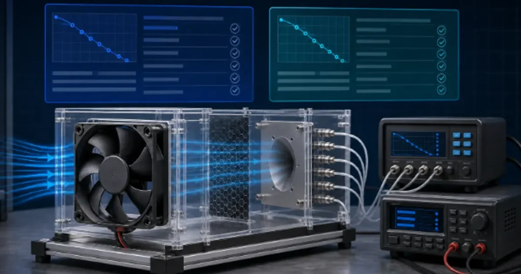
ISO 5801 and AMCA 210 in brief
ISO 5801:2017, together with Amendment 1:2025, covers fan performance testing using standardized airways. The current US joint method is ANSI/AMCA 210-25 / ANSI/ASHRAE 51-2025. Both address the measurements needed to establish fan aerodynamic performance, including airflow, pressure, speed, power and air density.
The documents have been progressively harmonized, but they remain separately maintained standards. Detailed terminology, allowed setups, calculations and reporting requirements can differ. There is no reliable universal factor that converts every ISO 5801 curve into an AMCA 210 curve.
| Question | ISO 5801 | AMCA 210 / ASHRAE 51 |
|---|---|---|
| Primary purpose | Standardized laboratory measurement of fan aerodynamic performance | Standardized laboratory method for fan aerodynamic performance rating |
| Typical market use | International projects and specifications | US specifications and AMCA-related rating work |
| Useful to compact fan buyers? | Yes, when the test setup and reported quantities match the product | Yes, under the same condition |
| Does the name alone prove certification? | No | No |
Note: Tested according to AMCA 210 does not mean AMCA certified. A test method, an accredited laboratory and a certified rating program are three different claims.
Why this matters for compact AC, DC and EC fans
LINKWELL supplies compact axial and centrifugal cooling fans for electrical cabinets, refrigeration equipment, industrial automation and other equipment-level applications. In these systems, the fan is rarely operating in an empty room. Air must pass through a grille, filter, heat exchanger, cabinet opening or a crowded internal path.
This is where test context becomes important. A free-air airflow value tells you what the fan can move at very low external resistance. It does not tell you the airflow remaining after the fan is installed behind a filter. For that decision, you need a complete airflow-pressure curve and a realistic estimate of system resistance.
A standard test method makes the curve more reproducible. It does not reproduce every cabinet. The final equipment still needs thermal or airflow validation with its production panels, guards, filters and heat-producing components in place.
The test configuration can change the curve
Both standards use defined airway arrangements. A fan may be tested with a free inlet and free outlet, with a duct on one side, or with ducts on both sides. These arrangements are commonly grouped as installation categories A through D.
| Category | Inlet | Outlet | Compact cooling example |
|---|---|---|---|
| A | Free | Free | A frame fan moving air between two open spaces |
| B | Free | Ducted | An open intake feeding a defined discharge airway |
| C | Ducted | Free | A defined inlet airway with open discharge |
| D | Ducted | Ducted | A fan evaluated between controlled inlet and outlet sections |
The category letter is only the beginning. Ask which test figure was used and what was attached to the fan. An inlet ring, guard, mounting plate or housing can change the incoming flow and the effective discharge area. If one supplier tests a bare impeller assembly and another tests the production fan with its housing, the curves do not describe equivalent products.
Compare the pressure definition before comparing the fan
Fan static pressure and fan total pressure are related, but they are not interchangeable. Total pressure includes the relevant velocity-pressure contribution. At a compact fan outlet, velocity can be high enough for that difference to affect the apparent pressure margin.
Before placing two curves on the same chart, check:
- Whether the vertical axis is static pressure or total pressure.
- Whether the pressure is stated across the fan or at another measurement location.
- Whether the production outlet area and accessories were included.
- Whether the curve was measured or converted to another air condition.
If your equipment calculation is based on static resistance, use compatible static-pressure data. The guide to static pressure vs total pressure explains this distinction in more detail.
Airflow, pressure and power must come from one operating point
Maximum airflow and maximum pressure are opposite ends of a fan curve. They are not delivered at the same time. Free-air airflow occurs near minimal pressure. Maximum pressure occurs near zero or very low airflow.
For a compact cooling fan, find the point where the fan curve intersects the estimated system curve. At that point, record airflow, pressure, speed, electrical input and noise. Do not compare one fan at free air with another fan at a restrictive operating point.
The fan curve guide shows how to locate this point, while the system resistance guide explains why a filter or grille moves it.
Power measurement is different for AC, DC and EC fan comparisons
For compact cooling fans, the most useful buyer-level value is usually electrical input at the product terminals. This includes the losses inside the supplied fan and its integrated electronics. It lets you compare the power your equipment must actually provide.
That boundary must still be stated. A DC fan tested at one voltage and duty command should not be compared with an EC fan tested at another speed without matching the airflow-pressure duty. A variable-speed model may also consume different power at the same command percentage because the command-to-speed mapping is model-specific.
When reviewing data, confirm:
- Supply voltage and frequency for AC or EC models.
- Supply voltage and control duty for DC models.
- Actual rotational speed during the test.
- Whether controller or external power-supply losses are included.
- Whether input is measured at the same airflow-pressure point.
Air density and temperature affect pressure results
Pressure and aerodynamic power depend on air density. Density changes with temperature, altitude, barometric pressure and humidity. A curve corrected to standard air may overstate the pressure available in a hot, high-altitude enclosure if you use it without correction.
For typical cabinet and refrigeration projects, provide the expected inlet-air temperature and installation altitude. Ask whether the published curve represents measured laboratory air or a converted reference condition. This matters more when the design has little pressure or temperature margin.
Accessories and installation details often matter more than the standard name
A standardized curve can still fail to predict your installed airflow if the production air path is poorly represented. Common differences include:
- A finger guard or louver added after the fan test.
- A filter tested clean but used until heavily loaded.
- A cabinet wall positioned too close to the inlet.
- A heat exchanger producing uneven resistance across the fan face.
- Cable bundles or components blocking the discharge.
- Multiple fans interacting through the same enclosure opening.
Ask for performance data for the assembly you plan to buy, then validate the complete equipment. A standard tells you how a laboratory measurement was controlled; it does not guarantee the temperature of your components.
A practical compact fan data checklist
| Data to request | Why you need it |
|---|---|
| Exact model and tested configuration | Confirms that the curve represents the purchased fan, housing and accessories |
| Test method and edition | Identifies the measurement framework without implying certification |
| Test setup or installation category | Shows the inlet and outlet boundary conditions |
| Complete airflow-pressure curve | Lets you find the operating point under resistance |
| Static or total pressure | Prevents mixing different pressure quantities |
| Voltage, frequency, command and speed | Makes AC, DC and EC results comparable |
| Electrical input at the operating point | Supports power-supply and efficiency decisions |
| Air density or test-air condition | Allows correction for altitude and temperature |
| Measurement tolerance or uncertainty | Prevents treating a curve line as an exact guarantee |
How to validate a fan inside your equipment
Begin with the published curve and your estimated resistance. Select a candidate operating point with margin for filter loading, production variation and environmental conditions. Then install the fan with its actual guard, filter, connector and control settings.
Run the equipment at a representative heat load. Measure the temperature at the components that actually limit operation, not only the air temperature near the fan. If airflow or pressure is measured, use a method suitable for the opening or duct rather than one velocity reading at the center of a grille.
Repeat the test at the expected supply tolerance, highest inlet temperature and end-of-service filter condition. For variable-speed fans, confirm both the cooling result and electrical input across the control range.
What LINKWELL needs for a meaningful fan comparison
When requesting a LINKWELL fan recommendation, provide the available mounting size, voltage, airflow direction, target airflow, estimated system pressure, inlet temperature, altitude and control requirement. Include drawings or photographs showing the inlet, outlet, filter and nearby components.
LINKWELL can then compare suitable product curves and configuration options against the stated duty. If your project requires testing to a named standard or third-party certification, specify the exact standard, edition, model scope and documentation requirement before samples are approved. Do not assume that a general product-family statement applies to every model.
Frequently asked questions
Is ISO 5801 better than AMCA 210 for compact cooling fans?
Neither is universally better. The more useful result is the one produced with a current method, clear pressure definition, traceable setup and a configuration relevant to the fan you will install.
Can I compare an ISO 5801 curve directly with an AMCA 210 curve?
Only after matching the test configuration, pressure quantity, air density, speed, voltage, accessories and power boundary. Similar units are not enough.
Does AMCA 210 mean the cooling fan is AMCA certified?
No. AMCA 210 is a performance test method. AMCA certification is a separate program and must be supported by the applicable certification scope and published rating.
Why is installed airflow lower than the datasheet value?
The datasheet maximum may represent free-air conditions. Filters, grilles, heat exchangers, restricted clearance and internal components add system resistance and move the operating point to lower airflow.
What is the most important document to request?
Request the complete airflow-pressure curve for the exact fan and tested assembly, together with voltage, speed, pressure definition and test condition. One maximum airflow value is not enough for equipment selection.

