
An intake filter fan and an exhaust filter normally work together rather than compete for the same job. The intake filter fan contains the powered fan that draws ambient air through filter media and pushes it into the enclosure. The exhaust filter is usually a passive outlet that lets heated air leave while helping protect the opening from dust and splashing.
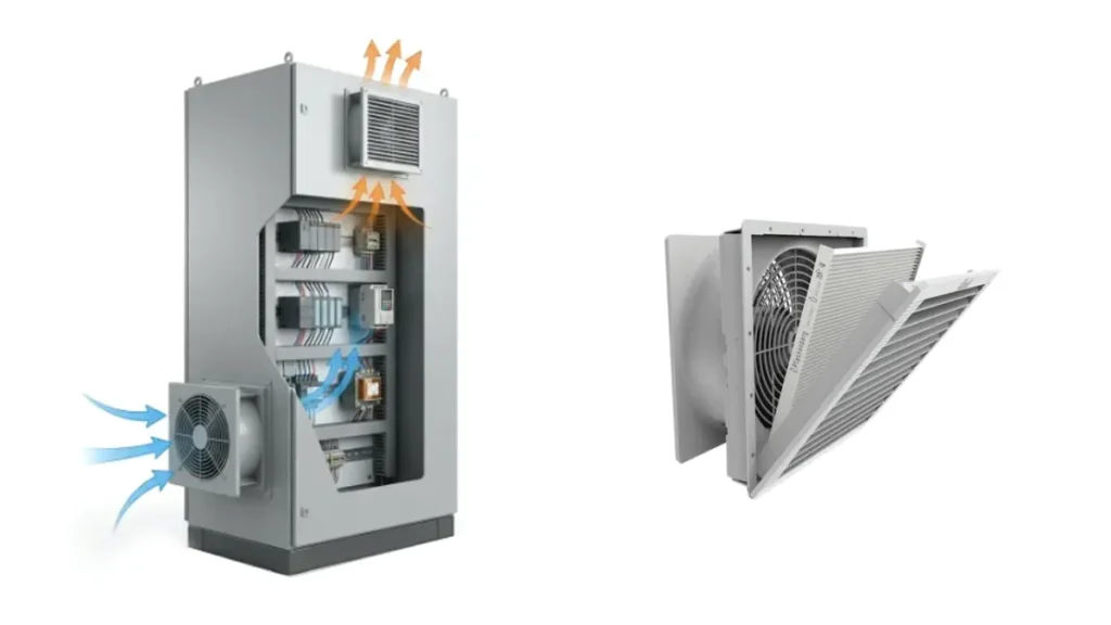
For many dusty industrial environments, the usual arrangement is a low-mounted intake filter fan and a high-mounted exhaust filter on the opposite side. This creates a defined airflow path and can maintain slight positive pressure, reducing the tendency for unfiltered air to enter through door gaps and cable openings.
Key Takeaways
- An intake filter fan and an exhaust filter are normally parts of one airflow system, not competing alternatives.
- Filtered positive-pressure airflow helps limit dust entry through small gaps, but it does not make the cabinet dust-tight.
- An exhaust fan creates negative pressure and can pull unfiltered air through cable entries and door gaps.
- The exhaust opening must pass the required air at low resistance; a small passive outlet can throttle a large intake fan.
- A low intake and a high outlet on the opposite side is a useful starting layout, then you must check the real component arrangement.
- Commission the finished cabinet with the doors closed and the filter fitted.
What Is the Difference?
| Feature | Intake Filter Fan | Exhaust Filter |
|---|---|---|
| Main function | Actively moves filtered ambient air into the enclosure | Provides a passive path for warm air to leave |
| Powered fan | Yes | Normally no |
| Typical location | Lower part of the cabinet on the cooler side | Higher on the opposite side |
| Pressure effect | Can create slight positive cabinet pressure | Relieves the pressure created by the intake fan |
| Effect on airflow | Creates the driving pressure and airflow | Adds outlet resistance and influences the operating point |
| Selection data | Voltage, frequency, fan curve, airflow, cutout, noise, filter, and IP level | Open area, pressure drop, filter media, cutout, and IP level |
The wording can be confusing because fan filter may refer to a filter mounted on a fan, while filter fan usually describes the powered cabinet assembly. In this article, intake filter fan means the powered inlet unit and exhaust filter means the passive outlet assembly.
Why Intake Ventilation Is Common in Dusty Cabinets
When the fan pushes more filtered air into the cabinet than escapes through unintended leakage, internal pressure rises slightly above ambient. Air then tends to move outward through small gaps. That outward leakage helps keep unfiltered dust from being pulled through the same gaps.
This does not make the cabinet dust-tight. The amount of positive pressure changes with fan airflow, filter loading, outlet resistance, door sealing, and other openings. A blocked intake filter can reduce or eliminate the pressure advantage even while the fan continues to run.
Positive-pressure filtered ventilation is useful only when the ambient air itself is suitable for the equipment. If the air carries corrosive gas, conductive dust, oil mist, or excessive moisture, filtering ordinary particulates may not provide enough protection.
What Happens If You Use the Fan as an Exhaust?
You can mount a fan to pull warm air out, but the pressure inside the enclosure becomes negative unless the inlet is designed to provide an equal filtered flow. Negative pressure encourages air to enter through every available gap. If door seals, cable openings, or unused holes bypass the inlet filter, dust can accumulate inside the cabinet even when a filter is installed elsewhere.
An exhaust-fan arrangement can work when the enclosure is designed with controlled, adequately sized, filtered inlet openings and the contamination risk is acceptable. You still need to check the full pressure path. The fan sees the combined resistance of the inlet media, cabinet, outlet grille, and any ducting.
Do not reverse a filter fan simply because the fan frame fits both directions. Confirm that the grille, filter, gasket, water-shedding geometry, wiring, and protection rating remain valid in the intended orientation.
How the Exhaust Filter Changes Fan Airflow
The exhaust filter is passive, but it is not aerodynamically neutral. Air must pass through its grille and media, creating pressure drop. A small or heavily loaded outlet increases cabinet pressure and reduces the airflow of the intake fan.
Your fan’s operating point is the intersection of its P-Q curve and the system-resistance curve. When you add a more restrictive outlet, that intersection moves toward lower airflow. This is why a free-air rating should not be used as installed performance.
Some LINKWELL fan filter configurations list airflow with one or more matching outlet filters. Use data for the exact model, voltage, frequency, filter media, and outlet arrangement. A second outlet can reduce resistance by adding effective area, but it will not automatically double airflow.
Recommended Airflow Layout
Place the intake filter fan in the lower third of the cabinet where it can draw relatively cool ambient air. Put the exhaust filter high on the opposite side. This layout uses the natural tendency of warmer air to rise and gives the forced airflow a longer path through the enclosure.
Position the openings so air crosses the main heat sources. A large mounting plate, VFD, cable duct, or tightly packed terminal block can split or block the flow. Avoid placing the intake and outlet so close together that the air leaves before reaching the equipment.
Installation height is not the only factor. Check nearby walls, machine guards, adjacent cabinets, and stored materials. External blockage at the grille can be as damaging as an internal obstruction.
How to Size the Intake and Exhaust Together
Start with the heat load and allowable temperature rise to calculate the required airflow. For an approximate metric result near normal room conditions and sea level:
Required airflow (m3/h) = 3.0 x heat load (W) / allowable temperature rise (deg C)
Then select the intake filter fan from its pressure-airflow curve at the expected resistance. Include the intake media, exhaust filter, grilles, panel openings, and internal path. Confirm that the outlet is large enough to avoid excessive backpressure at the target flow.
A design margin may be appropriate for uncertainty, altitude, future heat load, and filter loading, but do not replace engineering data with one generic percentage. The dedicated fan filter airflow calculation explains the unit conversions and operating-point checks in more detail.
Choosing the Correct Arrangement
| Operating Condition | Preferred Starting Point | Reason |
|---|---|---|
| Indoor cabinet with moderate dust | Low intake filter fan plus high exhaust filter | Creates a controlled path and can maintain positive pressure |
| Cabinet with many unsealed penetrations | Improve sealing before relying on filtered ventilation | Excess leakage weakens pressure control and airflow distribution |
| Ambient temperature at or above the internal limit | Closed-loop cooling evaluation | Open-loop ventilation cannot cool below ambient |
| Conductive, corrosive, oily, or very wet atmosphere | Contamination review and possibly sealed cooling | A particulate filter may not control the actual hazard |
| Heat sources concentrated near the top | Low intake with outlet positioned to sweep the hot zone | Reduces stagnant hot pockets |
| Existing exhaust-fan design | Verify filtered inlet area and bypass leakage | Negative pressure can draw contaminants through gaps |
Common Design Mistakes
- Using an intake fan without providing an adequate exhaust path
- Using an exhaust fan with no controlled filtered inlet
- Selecting both components only by nominal outside dimensions
- Comparing required airflow with the fan’s free-air value
- Mounting intake and exhaust too close together
- Blocking the grilles with cables, plates, walls, or adjacent equipment
- Ignoring the outlet filter during maintenance
- Assuming an IP-rated component gives the entire cabinet the same rating
- Using open-loop ventilation where ambient air is hotter than the target cabinet temperature
LINKWELL Fan Filter Configuration Support
LINKWELL’s LK32, LK66, FK55, and FF series support different cabinet fan filter layouts and serviceable filter arrangements. The correct pairing depends on airflow, voltage, cutout, protection, media, and outlet resistance. Confirm the selected model’s data rather than combining an unmatched fan filter and outlet grille.
For broader thermal planning, review LINKWELL’s electrical enclosure cooling solutions. If your layout requires a standalone fan behind a custom grille, compare available AC cooling fans and DC cooling fans.
Send your heat load, cabinet drawing, voltage, and environmental conditions to LINKWELL for a configuration review.
Positive vs Negative Pressure in Real Cabinets
When a filtered intake fan moves slightly more air into the enclosure than can leave through uncontrolled gaps, the cabinet operates at a small positive pressure. Air tends to move outward through those gaps, which helps reduce unfiltered dust entry. This is the main reason an active filtered intake with a passive exhaust is a common arrangement in indoor control panels.
Positive pressure is not the same as a sealed or certified dust-proof cabinet. Opening the door, a damaged gasket, an unused cable hole, or an undersized filter can still admit contamination. The pressure also changes as the intake mat loads with dust. Your maintenance plan must preserve both airflow and sealing.
An exhaust fan reverses the pressure relationship. It can remove heat effectively, but the resulting negative pressure draws make-up air through every available opening. Unless all those openings are properly filtered and sealed, dust may bypass the intended intake. That can be acceptable in a clean room or in a design with a controlled filtered inlet, but it needs to be a deliberate choice.
Four Practical Layout Examples
| Cabinet situation | Useful starting arrangement | Risk to check |
| VFD or PLC cabinet with heat distributed from low to high | Filtered intake low on one side, passive outlet high on the opposite side | Drives, wire ducts, or shelves may block the diagonal path |
| Divided cabinet with horizontal or vertical partitions | Provide a defined air path through each hot compartment; use internal circulation if required | One compartment may receive most of the flow while another becomes a hot spot |
| Dusty indoor production panel | Active filtered intake with a generously sized filtered outlet | Dirty media can remove the positive-pressure advantage and reduce cooling |
| Wet, corrosive, outdoor, or ambient-hot location | Review sealed cooling before selecting either fan arrangement | Ventilation may introduce moisture or corrosive air and cannot cool below ambient |
A low-to-high diagonal path uses the natural tendency of warm air to rise, but buoyancy is usually much weaker than forced airflow. Component placement still controls the result. Keep the intake away from a nearby hot exhaust, leave clear space behind the fan and outlet, and avoid placing both units where air can travel directly between them without crossing the heat sources. See cabinet fan airflow direction for a fuller layout method.
How to Size the Exhaust Opening
The passive exhaust is part of the same system as the intake fan. If its usable open area or filter is too restrictive, static pressure rises and the delivered airflow falls. A large intake fan paired with a small outlet does not create the airflow shown in the fan free-air rating.
Compare supplier pressure-drop data for both the intake and exhaust components at the required airflow. Remember that the nominal grille dimensions are not the same as the net free area: the frame, louvers, protective grid, and media occupy part of the opening. Include the cabinet interior in the resistance estimate as well.
If exact system data is not available during early design, use an exhaust with a larger effective flow area than the intake and confirm the result by test. Do not rely on a universal area ratio because filter construction and grille geometry vary. If the outlet must be compact, the fan selection needs enough pressure capability for that restriction. Our cabinet cooling fan sizing guide explains how thermal demand and resistance come together.
Commissioning Checklist for Intake and Exhaust Balance
- Run the equipment at a representative load with the enclosure closed and the production filters installed.
- Confirm the intended fan direction from airflow, not only from blade appearance or motor rotation.
- Check that air crosses the heat-producing components and leaves through the planned outlet. Investigate dead zones and short-circuit paths.
- Measure ambient and internal temperatures after they stabilize. Record a clean-filter baseline for later maintenance.
- Inspect door seals, cable entries, blanking plugs, and mounting gaskets. A strong leak can defeat the intended pressure pattern.
- Check noise and vibration. Whistling at the outlet can indicate excessive velocity or a restrictive opening.
- Simulate the control sequence if a thermostat or controller starts the fan. Make sure the switch point and hysteresis suit the thermal limits.
If temperatures remain high, do not assume the answer is another exhaust fan. First check heat-load estimates, outlet resistance, filter loading, recirculation, and hot ambient air. Enclosure temperature control provides a broader diagnostic framework.
When Neither Arrangement Is Appropriate
Both intake and exhaust ventilation exchange cabinet air with the surrounding environment. If the ambient air contains conductive dust, salt spray, oil mist, corrosive vapor, or unacceptable humidity, moving more of it through the cabinet may shorten component life. Ventilation is also unable to maintain an internal temperature below ambient.
In these cases, review a closed-loop heat exchanger or enclosure air conditioner. The comparison in enclosure fan vs air conditioner can help you decide before the cabinet design and cutouts are fixed.
Frequently Asked Questions
Should a cabinet filter fan blow in or out?
It commonly blows filtered air into the lower part of the cabinet, with warm air leaving through a passive exhaust filter higher on the opposite side. This can support positive pressure and reduce unfiltered leakage.
Does an exhaust filter contain a fan?
Normally, no. It is a passive filtered outlet. Product terminology varies, so confirm whether the item includes a powered fan before specifying it.
Can I install the intake fan at the top?
You can when the equipment layout and external air source justify it, but a lower intake and higher outlet is a reliable starting point for many cabinets. Validate the actual path around the heat sources.
Why does adding an exhaust filter reduce airflow?
The grille and filter media add pressure drop. That extra system resistance moves the fan’s operating point to a lower airflow unless the outlet is sized to keep resistance low.
Is positive pressure enough to stop all dust?
No. It helps reduce unfiltered ingress through gaps, but performance depends on filter efficiency, sealing, airflow, pressure balance, particle size, and maintenance. It does not make the enclosure dust-tight.

