
A good electrical cabinet fan filter installation does more than hold a fan in a panel cutout. The intake and exhaust must create a useful path across the heat-producing equipment, the filter must remain serviceable, and the completed mounting must preserve the intended protection level.
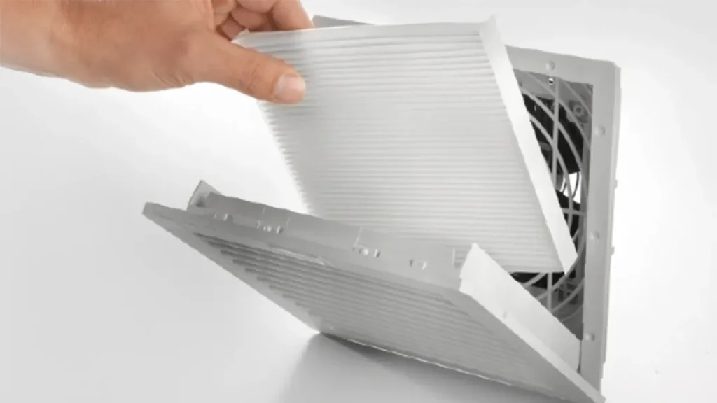
Plan the thermal system before cutting the cabinet. Once the openings are made, correcting poor placement, inadequate outlet area, or the wrong cutout becomes expensive. Confirm the product drawing and site electrical procedure for the exact model; the steps below are an engineering guide, not a replacement for those instructions.
Key Takeaways
- Complete the heat-load and airflow calculation before you cut the cabinet.
- Use a low intake and a high, opposite-side outlet as the initial layout unless the internal arrangement requires another path.
- Follow the exact model drawing for the cutout, orientation, gasket, and mounting method.
- The component rating does not automatically become the rating of the completed enclosure.
- Commission the system at representative load with the door closed, filter installed, and controls operating.
- Leave enough access to inspect and replace the filter without disturbing live parts or production wiring.
Before Installation: Confirm the Cooling Method
A filter fan exchanges cabinet air with the surrounding environment. Use it when ambient air is clean enough to enter after filtration and remains below the maximum internal temperature. It cannot cool below ambient temperature.
If the site contains conductive or corrosive dust, heavy oil mist, aggressive chemicals, high moisture, or ambient temperatures at or above the internal limit, evaluate a sealed heat exchanger or enclosure air conditioner instead. A higher airflow rating does not fix unsuitable ambient air.
Information You Need Before Cutting the Panel
| Input | What to Confirm | Installation Effect |
|---|---|---|
| Heat load | Actual watts dissipated inside the cabinet | Sets the required thermal airflow |
| Temperature limits | Maximum ambient and maximum allowable internal temperature | Defines the allowable temperature rise |
| Fan data | Voltage, frequency, current, P-Q curve, airflow, and direction arrow | Controls electrical compatibility and operating airflow |
| Filter arrangement | Intake media, exhaust filter, pressure drop, and service method | Changes system resistance and maintenance access |
| Mechanical drawing | Cutout, panel thickness, mounting depth, gasket, and clearances | Prevents fit and sealing failures |
| Protection target | Required IP level for the component and completed enclosure | Affects product choice, cutout quality, sealing, and validation |
| Cabinet layout | Heat-source position, cable ducts, partitions, and door swing | Determines intake and outlet placement |
Calculate the Airflow First
For an initial estimate near normal room conditions and sea level:
Required airflow (m3/h) = 3.0 x internal heat load (W) / allowable temperature rise (deg C)
If the cabinet dissipates 400 W, the maximum ambient temperature is 35 deg C, and the maximum internal temperature is 50 deg C, the allowable rise is 15 deg C. The estimated airflow is:
3.0 x 400 / 15 = 80 m3/h
This is not the free-air fan rating to order. Check the fan curve against pressure drop from the intake filter, exhaust filter, grilles, openings, and internal restrictions. Correct for altitude, unusually high air temperature, solar load, and uncertainty where applicable.
Choose Intake and Exhaust Positions
A reliable starting layout uses the filter fan as a low intake and a passive exhaust filter high on the opposite side. Cool air enters near the bottom, crosses the equipment, and carries heated air toward the upper outlet. The intake can create slight positive pressure, which helps reduce unfiltered air entering through small gaps.
Adjust the layout to the equipment. Air should sweep the drives, power supplies, transformers, and other major heat sources rather than bypassing them. Avoid positioning the intake and exhaust so close that air travels directly between the two openings.
Check both sides of the panel. Inside, allow space for wiring, terminal guards, duct covers, and the rear of the fan. Outside, make sure a wall, machine frame, adjacent cabinet, or stored material cannot block the grille. Leave enough clearance to open the cover and replace the filter mat.
Tools and Preparation
Use tools and protective equipment approved for the panel material and site. Typical preparation includes the model drawing or cutout template, measuring tools, a suitable cutting tool, drill, deburring tool, fasteners, cleaning equipment, and the electrical hardware specified for the fan circuit.
Remove or fully protect sensitive equipment from metal chips and cutting debris. Swarf left inside a cabinet can cause short circuits, insulation damage, or mechanical interference. Never cut above energized components.
Electrical Cabinet Fan Filter Installation Steps
- Isolate the cabinet. Follow the site lockout/tagout procedure and verify the required absence of voltage. Only qualified personnel should perform work that exposes electrical hazards.
- Verify the product and drawing. Match the fan filter model, voltage, frequency, airflow direction, cutout, panel thickness, gasket, exhaust filter, and mounting orientation to the approved design.
- Mark both openings. Use the manufacturer’s template or drawing. Check level, edge distance, internal clearance, external clearance, and the intended airflow path before making the first cut.
- Create the panel cutouts. Drill and cut using a method appropriate for the material. Keep chips out of the cabinet and protect the panel finish around the work area.
- Deburr and clean. Remove sharp edges that could damage the gasket, wiring, or installer. Restore corrosion protection where the panel-coating system requires it, then remove all debris.
- Fit the gasket and frame. Place the sealing components exactly as shown in the drawing. The mounting surface should be flat, clean, and undamaged.
- Install the filter fan in the correct direction. Check the airflow arrow rather than judging from blade shape. Seat the frame evenly and secure it using the specified clips or fasteners without distorting the housing.
- Install the exhaust filter. Confirm its orientation, cutout, gasket, and effective outlet area. A restricted outlet reduces the airflow of the intake fan.
- Make the electrical connection. Follow the fan wiring diagram, local electrical rules, grounding requirements, conductor sizing, overcurrent protection, and terminal-torque instructions. Keep wiring clear of moving parts and sharp edges.
- Inspect the complete assembly. Check cover engagement, gasket contact, fasteners, unused openings, cable entries, and service clearance. The component rating alone does not establish the completed cabinet rating.
- Commission the system. Restore power under the approved procedure. Verify airflow direction, fan sound, vibration, current, control response, alarms, and unobstructed inlet and outlet.
- Validate cabinet temperature. Run the equipment at a representative load and ambient condition. Measure temperatures near critical components, not only at one convenient point.
How to Verify Airflow After Installation
Start with a direction check at both grilles. Then compare the installed airflow with the project target using an appropriate measurement method. A handheld reading at one point on a grille may not represent the total volume flow, so follow the measurement method defined for the project or use a suitable airflow hood or test setup.
Record ambient temperature, internal temperature, equipment load, fan voltage, and filter condition during the test. If the cabinet runs hot, compare the measured operating conditions with the design case before replacing the fan.
Look for hot pockets behind large drives, near the top of enclosed compartments, and downstream of blocked passages. You may need a baffle, a relocated outlet, or an internal circulation fan even when total enclosure airflow appears adequate.
Protection Rating and Sealing Checks
An IP-rated fan filter does not automatically give the finished cabinet the same rating. The cutout, gasket compression, panel flatness, mounting, outlet filter, door seals, cable glands, and other penetrations all contribute.
Do not modify the grille, omit the gasket, reverse the assembly, or enlarge the cutout without confirming the effect on protection. If the project requires enclosure-level verification, arrange the applicable inspection or test after installation.
LINKWELL fan filter families include configurations up to IP54 and custom IP55 options for suitable requirements. Confirm the exact selected model and evidence before stating a protection rating in the cabinet documentation.
Common Installation Mistakes
- Cutting the panel before confirming airflow and model dimensions
- Installing the fan in the wrong airflow direction
- Using a high intake with a low outlet without evaluating the heat-source layout
- Placing intake and exhaust close enough to short-circuit the air
- Blocking the inside of the grille with wiring or a mounting plate
- Providing an exhaust opening that is too restrictive
- Leaving metal chips inside the enclosure
- Damaging or omitting the gasket
- Assuming free-air CFM equals installed airflow
- Failing to leave clearance for filter replacement
- Commissioning without recording load, ambient temperature, and cabinet temperature
Plan Filter Maintenance During Installation
Mount the fan filter where a technician can open the cover and remove the media without disconnecting equipment. If access requires dismantling a machine guard or moving the cabinet, routine filter maintenance is likely to be delayed.
Set an initial inspection interval based on dust exposure and operating hours, then adjust it using real filter condition, airflow, and temperature trends. Inspect the exhaust filter as well as the intake. Either can restrict the system.
Information to Send LINKWELL
For a model and installation review, provide:
- Internal heat load and temperature limits
- Cabinet dimensions, panel material, thickness, and drawing
- Proposed intake and exhaust positions
- Available voltage, frequency, and control method
- Required airflow and any known system resistance
- Dust, moisture, outdoor exposure, and required IP rating
- Required certification and target market
- Sample and annual production quantities
Review LINKWELL’s electrical enclosure cooling solutions and the available AC fan or DC fan platforms. For an application-specific recommendation, send your cabinet drawing and thermal data to LINKWELL.
New Cabinet Design vs Retrofit Installation
On a new cabinet, you can coordinate heat load, airflow path, fan size, outlet area, wiring, and service access before the panel is manufactured. That gives you the best chance of keeping cool air away from immediate short circuits and guiding it across the components that create the heat.
A retrofit needs more investigation. Before cutting, inspect both sides of the panel for rails, wire ducts, door stays, hinges, labels, structural returns, earth studs, and energized equipment. Check that the proposed opening will not weaken the panel or interfere with the door seal. Protect internal components from metal swarf and remove all debris before energizing. If you cannot isolate and protect the equipment, the work should not proceed.
For either case, calculate the required flow first using how to size a cooling fan for an electrical cabinet. Then confirm that the exact fan and outlet will deliver it against the resistance of the filters, grilles, and cabinet. Cutting a hole based only on frame size can leave you with an installation that is difficult to correct.
Wiring, Switching, and Monitoring Choices
Electrical work should follow the fan instructions, the cabinet design, applicable standards, and your site safety procedure. Confirm the nameplate voltage, AC frequency or DC polarity, current, protective device, conductor size, terminal method, and protective-earth requirement before connection. Do not assume that two fans with the same frame size have the same electrical rating.
A fan that runs continuously is simple, but a thermostat can reduce unnecessary operating time when heat is intermittent. Check that the thermostat contact or interposing relay is rated for the fan load, including starting characteristics, and place the sensor where it represents the critical cabinet temperature rather than the cold incoming-air stream. Define the switch-on point and hysteresis so the fan does not chatter.
If the application needs remote monitoring, decide what failure information is actually useful. Options may include a temperature alarm, airflow switch, differential-pressure indication, fan-speed signal, or controller status. Signal availability is model-specific; do not specify FG, RD, alarm, or PWM functions unless the selected fan supports them. You can review fan sensor options and 4-pin PWM fan control when the project requires feedback or speed control.
Commissioning Record for OEM Release
| Item to record | What to confirm | Why it matters |
| Fan and outlet identification | Model, voltage, frequency, airflow direction, filter media, and mounting orientation | Prevents a prototype result from being applied to a different production configuration |
| Mechanical installation | Cutout dimensions, edge condition, gasket contact, fasteners or clips, and service clearance | Supports sealing, repeatable assembly, and future maintenance |
| Electrical installation | Supply at the terminals, protection, control logic, current, rotation, and alarms | Confirms that the fan is powered and controlled as designed |
| Thermal test | Ambient temperature, internal temperatures, equipment load, stabilization time, and filter condition | Shows whether the completed cabinet meets its temperature limit |
| Airflow path | Intake and outlet direction, blocked zones, recirculation, and nearby hot-air sources | Verifies that air reaches the components rather than bypassing them |
| Release documents | Drawing revision, bill of materials, wiring diagram, maintenance interval, and spare-filter code | Keeps production and field service aligned with the validated design |
Test with the door closed, the final filters installed, and the equipment at a representative or worst credible load. Record a clean-filter temperature and airflow baseline. It gives maintenance teams something meaningful to compare as the media loads. For the complete path check, use cabinet fan airflow direction.
Troubleshooting After Startup
The fan runs, but the cabinet remains hot
Check the actual heat load, ambient temperature, filter condition, outlet area, airflow direction, and internal obstructions. Make sure hot outlet air is not being pulled directly back into the intake. If ambient is already at or above the target internal temperature, ventilation cannot meet the target; review the alternatives in enclosure fan vs air conditioner.
Airflow is much lower than expected
Compare the installed operating point with the free-air rating. A dense filter, small outlet, protective grille, tight internal path, or wrong supply can reduce flow. Also confirm that packaging, drawings, wiring, or a partition has not covered part of the path.
Dust appears inside the cabinet
Inspect the filter fit, gasket, door seal, cable entries, unused holes, and the balance between intake and exhaust. A cabinet under negative pressure can draw unfiltered air through leaks. Replace damaged or incorrect media, but do not claim the installed enclosure rating solely from the fan-filter component rating.
Noise or vibration appears after installation
Check panel stiffness, fastener engagement, frame seating, fan clearance, foreign objects, and flow restriction. A distorted cutout or uneven gasket can transmit vibration. Whistling may indicate a restrictive grille or gap; rubbing requires immediate correction.
The fan cycles too often
Review sensor placement, setpoint, hysteresis, local hot spots, and the control contact. A sensor in the incoming-air stream may not represent the equipment temperature, while a sensor too close to one hot component can cause rapid cycling. Document the final control settings in the OEM release record.
Frequently Asked Questions
Should a cabinet fan filter be installed at the top or bottom?
A low filtered intake with a high outlet on the opposite side is a reliable starting point. Adjust the layout so airflow crosses the actual heat sources and is not blocked by internal components.
Which way should the fan blow?
For positive-pressure filtered ventilation, the fan normally blows filtered air into the cabinet. Always confirm the airflow arrow on the selected model.
Can I cut the cabinet opening from the product’s outside dimensions?
No. Use the approved cutout drawing or template. The outside frame size, opening size, mounting depth, and fastener positions are different dimensions.
Do I need an exhaust filter?
You need an adequate outlet path. A matching exhaust filter is commonly used to provide a protected outlet and support the cabinet’s pressure arrangement. Include its resistance in the airflow calculation.
How do I know whether the installation provides enough cooling?
Verify airflow direction and operating conditions, then test the cabinet at representative heat load and ambient temperature. Measure temperatures near critical components and compare them with their allowable limits.

