
A centrifugal fan can look perfectly round and still be out of balance. If the impeller?s mass is not distributed evenly around its axis, rotation creates a repeating force. That force grows quickly with speed and can reach the bearings, motor, housing and equipment frame.
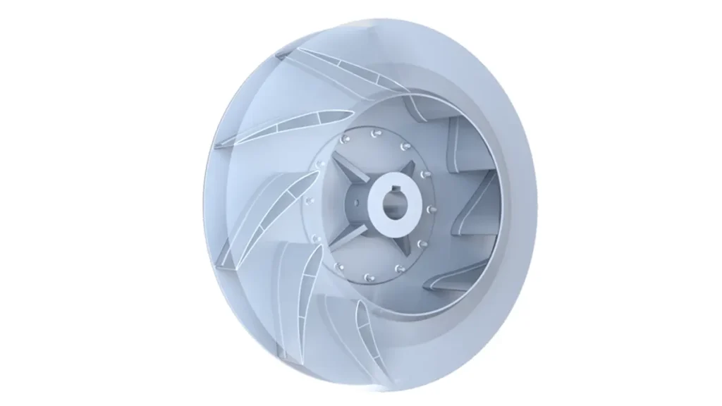
Balancing reduces the residual unbalance of the rotating assembly by adding, removing or redistributing a small amount of mass. It is an important factory process and a useful field correction in the right circumstances. It is not a cure for every vibration problem.
A fan with a well-balanced impeller can still vibrate because of a bent shaft, bearing damage, loose mounting, misalignment, resonance, aerodynamic stall, motor excitation or an installation that differs from the factory test. You need to separate rotor balance from complete-machine vibration before deciding what to correct.
Centrifugal fan balancing in one minute
| Question | Practical answer |
|---|---|
| What is balanced? | The impeller or rotating assembly, using one or more correction planes |
| What is measured? | Residual unbalance on a balancing machine, or vibration amplitude and phase during field balancing |
| Why does it matter? | Lower repeating force reduces avoidable vibration, bearing load, noise and structural fatigue |
| Does low unbalance guarantee low installed vibration? | No. The motor, bearings, shaft, base, resonance and airflow can create vibration independently |
| Is one balance grade right for every fan? | No. The applicable grade and vibration limit depend on fan application, speed, size, mounting and the agreed standard |
| Can you field-balance any blower? | No. Access, safety, wheel construction and measurement quality determine whether field correction is appropriate |
What unbalance does to a centrifugal fan
Imagine a small heavy spot on the impeller. As the wheel turns, that spot pulls outward and changes direction once per revolution. The rotating force is related to the unbalanced mass, its distance from the axis and the square of rotational speed. In simplified form:
Unbalance force is proportional to mass ? eccentricity ? angular speed?.
The speed-squared term matters. If the same unbalance remains and speed doubles, the resulting force can increase by roughly four times. That is why a wheel that seems acceptable during a slow hand check may vibrate badly at operating speed.
Repeated force can loosen fasteners, excite a flexible panel, increase bearing load and create fatigue in brackets or welds. It can also produce a strong vibration peak at one times running speed. None of those symptoms proves unbalance by itself, but they justify a structured check.
Static, couple and dynamic unbalance
| Condition | What it means | Typical correction approach |
|---|---|---|
| Static unbalance | The center of mass is offset from the rotation axis; the heavy point tends to settle downward when the rotor is free | One correction plane may be sufficient for a thin rotor |
| Couple unbalance | Two offset masses create a rocking couple even though the overall center of mass may lie near the axis | Requires corrections in two separated planes |
| Dynamic unbalance | A combination of static and couple effects, common in rotors with meaningful width | Dynamic spin balancing, normally using two-plane correction when the geometry requires it |
Most centrifugal impellers have enough axial width that dynamic behavior matters. ISO 21940-11 addresses the permissible residual unbalance, correction planes and tolerance allocation for rigid rotors. The exact procedure still depends on the wheel construction and balancing equipment.
Why centrifugal impellers become unbalanced
Manufacturing and assembly variation
Blade thickness, welds, hub position, casting or molding variation, coating and fasteners all change mass distribution. Factory balancing corrects the residual effect after the relevant components and finishing steps are complete.
Dust or material buildup
Sticky dust rarely deposits with perfect symmetry. A small uneven layer at a large radius can create a noticeable change. If you add a correction weight before cleaning the wheel, the fan may become unbalanced in the opposite direction when the deposit later falls off.
Erosion and corrosion
Abrasive particles remove material, while corrosion changes both mass and surface condition. The loss may be uneven from blade to blade. Balancing can reduce vibration, but it cannot restore a thinned or cracked impeller to a safe condition.
Impact damage, repair or loose parts
A bent blade, repaired weld, replaced fastener or moved balance weight can alter the mass distribution. Inspect structural condition and attachment security before running a balancing procedure.
Thermal or mechanical distortion
Uneven heating, shaft damage or an impeller mounted with dirt on the mating surface can shift the rotating geometry. Correct the fit or deformation first. Adding weight to compensate for a mounting error hides the cause and may make future service harder.
How factory centrifugal fan balancing works
1. Inspect and prepare the rotating assembly
The operator checks the impeller for damage, contamination, loose hardware and obvious runout. The wheel must be in the condition represented by the acceptance requirement. Paint, hubs and attached hardware can matter because they contribute mass.
2. Mount the rotor on the balancing machine
The fixture and arbor must locate the rotor repeatably. Dirt, poor fit or excessive fixture error can make a good wheel appear bad and can produce a correction that is wrong after installation.
3. Rotate and measure residual unbalance
The balancing machine measures the magnitude and angular location of the unbalance. Depending on rotor geometry, the process uses one or two correction planes. The target is an agreed residual unbalance or balance quality requirement, not a visual impression of smooth running.
4. Add or remove material
Correction may involve securely adding approved weights or removing a controlled amount of material at a permitted location. The method must suit the impeller material, speed and service environment. Improvised clips, adhesive weights or drilling in an unapproved area can create a safety risk.
5. Re-run and document the result
After correction, the rotor is measured again. The process repeats until the result meets the specified tolerance. For projects that require traceability, the record should identify the rotor or fan, speed, standard, balance grade or residual-unbalance limit, correction planes and final result.
6. Check the assembled fan when required
Rotor balancing and assembled vibration testing answer different questions. A factory run test can reveal problems introduced by the motor, bearings, shaft, housing, base or assembly. For critical applications, specify both requirements instead of using one as a substitute for the other.
Balance quality and vibration limits are not the same specification
ISO 14694 covers fan balance quality and vibration levels for defined industrial fan applications within its scope. ANSI/AMCA 204-20 also sets balance quality and vibration requirements by fan application category. ISO 21940-11 focuses more generally on balancing procedures and tolerances for rotors with rigid behavior.
These documents do not justify copying one grade into every purchase order. The appropriate requirement depends on application category, driver power, operating speed, mounting condition, test location and the consequence of vibration. An unnecessarily severe limit can add cost and test time without improving the actual equipment; a vague ?dynamically balanced? note may provide no measurable acceptance criterion.
| Requirement | What it controls | What must be stated |
|---|---|---|
| Rotor balance requirement | Permissible residual unbalance of the impeller or rotating assembly | Standard, grade or tolerance, maximum service speed, rotor mass and correction-plane basis |
| Factory vibration requirement | Vibration of the assembled fan under defined test conditions | Speed, mounting, measurement locations, directions, amplitude unit and filter condition |
| Installed vibration requirement | Behavior after the fan is mounted in the customer?s equipment | Foundation or panel condition, piping or duct connection, operating point and acceptance method |
State whether the fan is tested rigidly or flexibly mounted and whether vibration is measured at the fan housing, motor or bearing locations. Results from different setups are not directly interchangeable.
Symptoms of unbalance?and what else can look similar
Unbalance often produces a dominant vibration component at one times fan rotational speed. Amplitude may rise as speed increases, and phase can be reasonably stable when the operating condition is steady. That pattern is useful evidence, but it is not a complete diagnosis.
| Observation | Possible cause | First check |
|---|---|---|
| Strong vibration at 1? fan speed | Impeller unbalance, eccentric fit or shaft runout | Clean and inspect the wheel; verify mounting and vibration phase |
| High 2? running-speed component | Misalignment, looseness or bent shaft | Check fit, fasteners, shaft condition and alignment |
| Broadband high-frequency vibration | Bearing damage, rubbing or turbulence | Inspect bearings and clearances; listen for contact |
| Vibration peaks only in one speed band | Structural resonance | Run-up or coast-down test and mounting-stiffness review |
| Noise and vibration change with damper or filter condition | Aerodynamic stall, recirculation or unstable operating point | Check the fan curve, system resistance and inlet/outlet blockage |
| Motor-frequency-related vibration | Electrical excitation or motor issue | Compare fan and motor speeds; review electrical and motor condition |
| Vibration increases after cleaning | Old balance correction compensated for buildup, or material was removed unevenly | Inspect previous weights and rebalance the clean rotor if needed |
A vibration spectrum, phase measurement and physical inspection are much more useful together than an overall vibration number alone. If your main problem is installed vibration, start with the broader checklist in How to Reduce Vibration in Industrial Cooling Fans.
When field balancing makes sense
Field balancing can be useful when a large or installed fan is structurally sound, the vibration signature points to unbalance, the rotor can be accessed safely and a qualified technician can measure amplitude and phase. It accounts for the rotor in its actual bearings, shaft and installation.
It is a poor first step when the wheel is cracked, badly corroded, rubbing, loose on the shaft or covered with removable material. It is also inappropriate when you cannot attach a correction weight securely or verify clearance at operating speed.
Do not field-balance a running fan casually
Balancing work exposes people to rotating equipment and stored energy. Shut down and isolate power before inspection or weight changes, follow the equipment manufacturer?s procedure, and use trained personnel with suitable instrumentation. Guards must be restored before normal operation. Small enclosed high-speed blowers are often safer and more economical to replace or return to the manufacturer than to modify in the field.
How to preserve balance in service
- Keep filters and upstream separators in the intended condition so contamination does not build unevenly.
- Inspect the wheel at a frequency based on the airstream, hours and consequence of failure.
- Clean the impeller uniformly; do not scrape one blade more aggressively than the others.
- Check that balance weights, hub fasteners and mounting hardware remain secure.
- Investigate a change in vibration trend instead of waiting for a shutdown threshold.
- After a blade repair, coating change or component replacement, review the need for rebalance.
- Correct resonance, misalignment and bearing faults at their source rather than masking them with weights.
What OEM buyers should specify
?Dynamically balanced? sounds reassuring, but it does not tell the supplier what result you will accept. A clear RFQ separates rotor balance from assembled vibration and defines the test condition.
| RFQ item | Why it matters |
|---|---|
| Fan model, impeller drawing and operating orientation | Defines the rotating assembly and installation |
| Normal and maximum operating speed | Balance tolerance and force are speed-dependent |
| Airflow, pressure and expected operating range | Aerodynamic instability can be mistaken for balance trouble |
| Applicable balance or fan-vibration standard | Creates a shared acceptance basis |
| Required balance grade or residual-unbalance limit | Makes the rotor requirement measurable |
| Factory vibration limit and unit | Defines the assembled-fan result |
| Rigid or flexible test mounting | Mounting changes measured vibration |
| Measurement locations and directions | Prevents incompatible test records |
| Filter-in or overall measurement and frequency range | Clarifies whether the result isolates running speed or includes broader vibration |
| Report and traceability requirement | Links the test result to the delivered fan or rotor |
Do not specify a stricter grade simply because the number looks better. Select the application category and acceptance limits with the fan manufacturer or vibration engineer. Critical semiconductor, laboratory, transport or process equipment may justify different requirements from a general cabinet cooling fan.
LINKWELL manufactures centrifugal cooling fans for industrial equipment. For a project review, provide the fan duty, speed, mounting condition, vibration expectation and any reporting requirement so the appropriate production and test basis can be confirmed.
Factory acceptance checklist
- The fan and test report use the same serial, batch or traceability reference.
- The test speed matches the specification or the difference is clearly stated.
- The balance standard and grade or residual-unbalance limit are identified.
- Correction weights are permanent, secure and clear of the housing.
- The impeller has no visible damage, rub marks or loose parts.
- Assembled vibration is measured under the agreed mounting condition.
- Amplitude unit, peak or RMS convention, filter condition and measurement locations are recorded.
- The report does not present a rotor balance result as proof of installed-equipment vibration.
FAQ
What is centrifugal fan balancing?
It is the process of measuring and correcting uneven mass distribution in the impeller or rotating assembly so the residual unbalance falls within an agreed tolerance.
What is the difference between static and dynamic balancing?
Static balancing corrects a heavy spot in a single plane and is most suitable for thin rotors. Dynamic balancing rotates the rotor and can correct both static and couple unbalance in two planes. Centrifugal impellers commonly need dynamic evaluation because they have meaningful width.
Does an unbalanced fan always vibrate at 1? RPM?
Unbalance commonly creates a strong 1? running-speed component, but other faults can do the same. Eccentric mounting, shaft runout and some looseness can look similar. Confirm with phase, inspection and other vibration evidence.
Can cleaning fix fan unbalance?
Yes, when uneven buildup is the cause. Clean the wheel uniformly and inspect it before adding weights. If vibration remains, check for erosion, damage, fit and other mechanical or aerodynamic causes.
How often should a centrifugal fan be balanced?
There is no universal calendar interval. A sound impeller does not need routine weight changes. Inspect and investigate when vibration trends change, after significant repair or coating work, or when contamination and erosion alter the wheel.
Can balancing extend bearing life?
Reducing excessive unbalance removes one avoidable source of cyclic bearing load, so it can support longer service life. It cannot compensate for poor lubrication, contamination, electrical bearing damage, misalignment or the wrong bearing selection.
What balance grade should I specify for a centrifugal fan?
Use the grade or limit appropriate to the fan application category, speed, size and agreed standard. Do not assume G 2.5 or any other grade is universal. Ask the manufacturer or a qualified engineer to align the balance requirement with the assembled-vibration acceptance condition.
Should I balance the impeller or test the complete fan?
For critical equipment, you may need both. Impeller balancing controls residual rotor unbalance. A complete fan test checks the combined effect of the rotor, shaft, bearings, motor, housing and base under a defined factory setup.

