
When one fan cannot meet the cooling target, adding a second fan seems like an easy fix. You can place the fans side by side so they share the airflow, or arrange them one after another so the same air passes through both. Those layouts are called parallel and series operation.
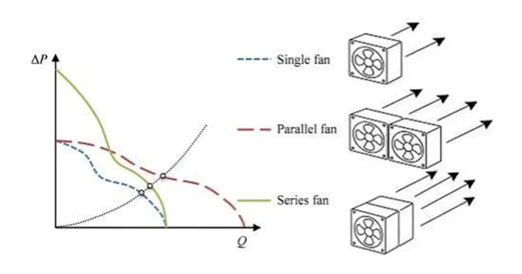
The basic rule is useful: parallel fans increase available airflow, while series fans increase available pressure. The installed result, however, depends on the combined fan curve and the resistance curve of your enclosure, filter, heat exchanger or duct. Two fans rarely give you a clean twofold improvement at the operating point.
For industrial equipment, the choice also affects noise, electrical load, fault behavior and maintenance. A parallel array may provide capacity and redundancy. A poorly planned series pair may add turbulence instead of useful pressure. You need to evaluate the complete system rather than count fans.
Selection note: Choose the arrangement from the combined fan curve and system curve. Do not treat twice the free-air flow or twice the shut-off pressure as installed performance.
Fans in parallel vs series: the quick answer
In parallel operation, two or more fans draw from a common inlet region or plenum and discharge into a common outlet region. Each fan handles part of the total flow while operating against approximately the same system pressure.
In series operation, the outlet air from one fan enters the next stage. The same mass flow passes through both fans, and each stage contributes pressure to overcome the system resistance.
| Comparison | Fans in parallel | Fans in series |
|---|---|---|
| Main purpose | Increase available airflow | Increase available pressure |
| How the combined curve is formed | Add fan airflow values at the same pressure | Add fan pressure values at the same airflow |
| Theoretical endpoint for two identical fans | Twice the free-air flow; similar shut-off pressure | Similar free-air flow; twice the shut-off pressure |
| Usually most useful | Low-resistance, high-volume systems | Higher-resistance airflow paths |
| Typical concern | Unequal load sharing or backflow through an idle branch | Swirl, turbulence and added restriction between stages |
| Failure behavior | Remaining fans may provide reduced flow | A stopped stage can restrict the active fan |
The endpoint values in the table describe the combined curve, not the duty point. If you are not comfortable reading pressure-flow data, start with How to Read a Fan Curve.
How combined fan curves are built
A fan curve plots the pressure a fan can produce at each airflow. The system curve plots the pressure your equipment requires at each airflow. The operating point is where those two curves cross.
To build a parallel curve for identical fans, choose a pressure value and add the airflow delivered by each fan at that pressure. If one fan delivers 300 CFM at 80 Pa, two identical parallel fans have a theoretical combined flow of 600 CFM at 80 Pa. Repeat that calculation across the curve.
To build a series curve, choose an airflow value and add the pressure contribution of each stage at that flow. If each identical fan develops 120 Pa at 300 CFM, the ideal combined curve reaches 240 Pa at 300 CFM. Interstage losses and inlet distortion must then be considered.
After building the combined curve, intersect it with the real system curve. That new intersection gives the predicted airflow and pressure. The U.S. Department of Energy notes that filters, ducts, bends, grilles and non-uniform flow can raise actual system losses above a simple component calculation. This system effect is one reason an installed result falls short of an ideal combined curve.
Use total pressure rather than casually adding static-pressure values when fan stages have different areas, duct velocities or inlet densities. For compact cooling fans with matched test conditions, manufacturer P-Q curves may already provide the most practical basis. Do not combine curves with different voltage, speed, air density or pressure definitions.
What changes when fans operate in parallel?
Parallel fans are placed side by side or connected to separate branches that feed the same air system. Because each fan sees roughly the same pressure difference, their airflow contributions are added at that pressure.
Two identical fans can theoretically provide twice the single-fan free-air flow at zero pressure. The maximum pressure of the parallel pair remains close to the maximum pressure of one fan. Between those endpoints, the useful gain depends on the system curve.
In an open or low-resistance enclosure, the new operating point may move far enough to the right to give a substantial airflow increase. In a restrictive system, the steeper system curve limits that movement. Adding a second parallel fan can then produce a surprisingly small gain.
What if the parallel fans are not identical?
Different fan curves mean different flow contributions at the shared pressure. One fan may carry most of the duty while the other operates near stall or contributes very little. If the system pressure exceeds what the weaker fan can produce, air may flow backward through that branch.
Matched models, matched control signals and similar inlet conditions make load sharing easier to predict. For large fan arrays, branch dampers, control logic and minimum-running-fan rules may be needed. For small equipment fans, the enclosure geometry and the open area around a stopped fan deserve the same attention.
What changes when fans operate in series?
Series fans are arranged so one fan works downstream of another. At a given airflow, the ideal combined pressure is the sum of the pressure developed by both stages. Two identical curves therefore produce twice the shut-off pressure at zero flow, while the free-air endpoint remains close to that of one fan.
The pressure increase is most useful when the airflow path has significant resistance. A filter, dense heat exchanger, long duct or narrow cooling channel can move the duty point into a region where a series pair delivers more airflow than one fan can maintain.
Why directly stacking axial fans can disappoint
The first axial fan leaves swirl and an uneven velocity profile. If the second fan sits directly against it, the downstream blades receive disturbed air rather than the uniform inlet condition used for the catalog curve. The result may be less pressure gain, more tonal noise and higher blade loading.
A straight section, flow straightener, properly designed spacing or an engineered counter-rotating assembly can improve the interaction. Two arbitrary fans placed face to face are not equivalent to a purpose-designed two-stage fan.
Both stages should be checked at the same mass flow, and the second fan?s inlet condition must remain within its limits. Temperature rise is normally small in compact cooling duties, but pressure, density and motor heating can matter in larger industrial systems.
Why two fans rarely double installed performance
The familiar ?double airflow? and ?double pressure? statements describe opposite endpoints of ideal curves for identical fans. Cooling happens between those endpoints, where the combined curve meets the system curve.
Several effects reduce the installed improvement:
- System pressure loss rises rapidly as airflow increases, often close to the square of flow for a fixed turbulent path.
- Guards, filters, heat exchangers, ducts and outlet openings add losses that may have been omitted from the first estimate.
- Fans mounted close together can receive non-uniform or swirling inlet air.
- Manufacturing tolerance, voltage drop and different control signals prevent perfectly matched speed and performance.
- Leakage and bypass paths can allow air to circulate without cooling the intended components.
- A fan working near stall may become noisy or unstable instead of adding useful flow.
Power also adds. Two fans may each draw a different current after the operating point moves, so use the power or current data across the curve when available. Do not assume twice the electrical input produces twice the cooling.
A single larger fan, a higher-pressure design or a better airflow path may outperform a two-fan arrangement with fewer failure points. Before adding hardware, check whether a larger vent, cleaner filter, smoother transition or less crowded inlet can lower fan system resistance.
Parallel or series at different system resistance levels
The system curve tells you which arrangement is likely to provide the larger benefit. It is more useful than choosing from the words ?airflow? and ?pressure? alone.
| System condition | Arrangement to evaluate first | Reason | What to verify |
|---|---|---|---|
| Open enclosure or low-resistance ventilation | Parallel | The system can accept a larger increase in flow without a steep pressure penalty | Outlet area, recirculation, noise and current |
| Moderate filter, grille or heat exchanger resistance | Compare both combined curves | Either flow capacity or pressure capability may move the duty point farther | Clean and loaded filter operating points |
| Dense heat exchanger, long duct or narrow channel | Series or a higher-pressure single fan | More available pressure may maintain useful flow against the steep system curve | Interstage losses, stall margin and motor power |
| Capacity plus fault tolerance | Parallel with fault analysis | Remaining fans may continue operating after one unit stops | Backflow, alarm logic and required degraded airflow |
| Very limited installation space | Reconsider the fan type or use a purpose-designed assembly | Stacking or crowding fans can destroy the expected curve benefit | Envelope, inlet clearance and prototype temperatures |
At medium resistance, there is no shortcut. Plot the parallel and series curves against the same system curve. If neither reaches the required duty with sensible margin, choose a different fan rather than adding another copy of the wrong one.
Industrial applications for series and parallel fans
| Application | Arrangement commonly evaluated | Main engineering check |
|---|---|---|
| Electrical enclosure or power electronics | Parallel panel fans for wide, low-resistance ventilation; higher-pressure fan or tested series layout for dense filters | Inlet and outlet area, component hot spots and loaded-filter duty |
| Heat exchanger or filtered cooling module | Push-pull fans across the restrictive core | Core pressure drop, plenum design, fan spacing and fouled condition |
| Telecom, UPS or energy-storage equipment | Parallel array with staging or speed control | Minimum airflow after a fan alarm and backflow through the stopped branch |
| HVAC or air-handling system | Parallel plenum fans for capacity and turndown; series stages for unusually high pressure | Plenums, dampers, control logic and the full system curve |
| Compact high-pressure cooling | Purpose-designed counter-rotating axial assembly | Use its tested curve; do not substitute two arbitrarily stacked fans |
If the path is restrictive from the start, compare the multiple-fan proposal with a centrifugal fan or a more suitable axial design. Changing the fan type can be cleaner than compensating for a poor match with extra units.
Airflow arrangement and electrical wiring are different
?Series? and ?parallel? can describe two different things: the physical air path and the electrical circuit. Do not assume one determines the other.
Two fans in a series air path are often connected electrically in parallel to the power supply so each fan receives its rated voltage. Connecting two DC fans electrically in series divides the supply voltage according to their changing electrical behavior. Startup can become unreliable, speed may not share evenly, and one fan fault can stop both units.
For AC or EC fans, follow the wiring diagram and control requirements for the exact model. Never improvise a series electrical connection merely because one fan is mounted behind another.
Important: A series airflow path does not require series electrical wiring. Each fan should normally receive its rated voltage, and the power, protection and control design must be checked separately.
Size the power supply and protective devices for the combined running current and startup behavior. If you use PWM control, confirm whether the control input can drive several fans and whether a common control ground is required. Do not tie tachometer or alarm outputs together unless their output type and controller input support it; separate monitoring channels are often safer.
Failure behavior, redundancy, noise and control
| Condition | Likely effect | What to design or test |
|---|---|---|
| One parallel fan stops | The operating point moves to lower total flow; the idle branch may allow bypass or reverse flow | Minimum safe airflow, fan alarm and branch backflow |
| One series fan stops | The active fan loses the second-stage pressure and must push through the stopped rotor | Fault-condition airflow and a possible bypass path |
| Several fans run at slightly different RPM | Broadband noise, blade-pass tones or beating may become more noticeable | Installed sound at normal and transition speeds |
| Fans are staged or speed-controlled | Part-load power and noise may fall, but the duty can move into an unstable region | Control sequence, stall margin, filter loading and temperature response |
Parallel fans are redundant only when the remaining units can meet the defined safe duty and the stopped branch does not steal too much airflow. A series pair is usually even more sensitive to a stopped stage. Test the degraded operating point instead of treating fan count as proof of redundancy.
More fans do not automatically mean more noise. Several slower fans may sound better than one high-speed unit, or they may create additional tones and turbulence. Compare one fan at full speed, multiple fans at reduced speed and a different single-fan selection at the most common duty.
How to choose and validate the arrangement
Use the following process before you release the mechanical layout or wiring harness:
- Define the required airflow from the heat load, temperature limit or ventilation target.
- Estimate or measure the system resistance at that flow. Include clean and loaded filters, grilles, heat exchangers, ducts, bends and internal obstructions.
- Obtain the complete P-Q curve for the exact fan model, voltage, frequency and control setting.
- Build the parallel curve by adding flow at equal pressure, or the series curve by adding pressure at equal flow.
- Add realistic interaction and interconnection losses rather than using the ideal curve as a guarantee.
- Find the new operating point where the combined curve intersects the system curve.
- Check power, current, sound, stall margin and the operating point with one fan stopped.
- Prototype the actual fan spacing, guards, filter and equipment geometry, then measure temperature or airflow at the worst ambient and supply condition.
AMCA?s fan-curve guidance reinforces that the duty point comes from the fan and system curves together. If your predicted performance depends on an endpoint printed in a catalog, the selection is not finished.
When a different single fan is the better answer
Choose a different fan when the combined arrangement only meets the duty with no margin, creates difficult inlet conditions, complicates service or costs more power than a properly matched unit. A larger axial fan may deliver the required low-pressure flow at lower speed. A centrifugal fan may provide the pressure needed by a restrictive path without stacking axial fans.
Also compare controllable DC fans and EC fans when the cooling load changes. Speed control can give a smoother capacity range than repeatedly switching fixed-speed fans on and off.
What to send your fan supplier
A useful RFQ lets the supplier model the duty instead of guessing from maximum airflow. Include:
- Required airflow and static or total pressure, with units.
- System curve or pressure-drop data at one or more airflow points.
- Clean and loaded filter resistance.
- Fan orientation, spacing, inlet clearance and a drawing of the airflow path.
- Supply voltage, frequency, allowable current and startup limits.
- PWM, analog control, tachometer and alarm requirements.
- Normal and worst-case ambient temperature, air density and contamination.
- Noise target and the measurement condition.
- Required airflow after one fan fails, if redundancy is part of the design.
- Annual quantity, approvals, connector, lead and OEM customization needs.
LINKWELL supplies industrial AC fans, DC fans, EC fans and centrifugal cooling solutions. Send the real duty point and equipment layout when you want to compare one larger fan with a parallel array or series arrangement. That information makes the recommendation far more useful than a request for ?double airflow.?
FAQ
Is it better to run fans in parallel or series?
Parallel is usually more useful when you need more airflow in a low-resistance path. Series is usually more useful when the system needs more pressure. The final choice must come from the combined fan curve and your system curve.
Do two fans in parallel double CFM?
Two identical fans theoretically double the free-air endpoint because their flow values are added at the same pressure. Installed airflow usually increases by less than two times because the higher flow creates more system pressure loss.
Do two fans in series double static pressure?
At zero flow, two identical ideal fan curves can reach about twice the single-fan shut-off pressure. At a working airflow, add the pressure from each curve and subtract interaction or duct losses. Directly stacked axial fans may deliver less than the ideal prediction.
Can different fan models operate in parallel?
They can, but their flow contributions will be unequal. The weaker fan may operate near stall or experience reverse flow if the shared system pressure is too high. Use the actual curves and check every planned fan combination.
Can different fans operate in series?
Yes, if both fans can handle the same mass flow and the inlet condition of the downstream fan is acceptable. Different sizes, outlet areas or air densities make simple static-pressure addition unreliable, so use total-pressure data and supplier review.
Is a push-pull fan arrangement the same as series operation?
It is a form of series airflow arrangement because one fan pushes air into a restriction and the other pulls from the downstream side. The heat exchanger or filter between them changes the interaction, so test the complete push-pull assembly rather than treating the fans as directly stacked.
Should two fans in a series air path be wired electrically in series?
Usually not. Each fan should normally receive its rated supply voltage, which often means the motors are electrically connected in parallel even though the air path is in series. Follow the wiring and control requirements for the exact fan.
Are parallel fans automatically redundant?
No. They provide redundancy only if the remaining fans can meet the defined safe duty and the stopped branch does not create excessive backflow. Include fan-failure detection and verify the degraded operating point.
Will more fans always increase noise and power?
Total electrical input generally rises because more motors are running, although lower-speed operation may improve system efficiency at some duties. Noise can rise, fall or change character depending on RPM, spacing, control and turbulence. Measure the assembled equipment.

