
For most ventilated electrical enclosures in dusty industrial spaces, slight positive pressure is the better starting point. A filtered intake fan pushes clean air into the cabinet, so air tends to leave through small gaps instead of pulling dust through them.
Negative pressure can still be useful when you need to draw heat toward a defined exhaust and the surrounding air is clean. Its main limitation is that every unsealed door seam, cable entry and unused opening can become an uncontrolled intake.
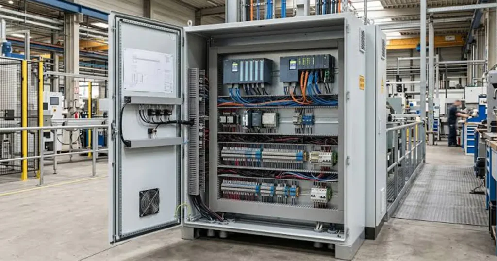
Pressure direction alone does not decide whether components stay cool. The fan must deliver enough airflow against the resistance of filters, guards, louvers and internal passages, and the air must cross the heat-producing components before it exits. This comparison applies to open-loop ventilation that uses ambient air. If the ambient air is too hot, corrosive, oily or too contaminated for practical filtration, a fan-only arrangement may not be suitable.
Pressure is the result of installed airflow
A cabinet does not become positive-pressure simply because it has an intake fan. It becomes positive only when the fan delivers more air into the enclosure than can leave through the intended outlet and other leakage paths at ambient pressure.
Likewise, an exhaust fan creates negative pressure only while it removes air faster than replacement air can enter through the planned intake and unsealed openings.
The result depends on actual installed airflow, not the number of fans or their maximum CFM labels. Filters, louvers, guards, cable congestion and small openings shift every fan’s operating point. Two identical fans can also deliver different airflow if one works behind a filter and the other exhausts through a relatively open grille.
Pressure difference and cooling airflow should be measured separately. A small pressure difference can control leakage direction while the airflow path across critical components determines temperature.
How positive and negative pressure behave
| Design factor | Positive-pressure enclosure | Negative-pressure enclosure |
|---|---|---|
| Typical fan position | Filtered intake fan pushes ambient air into the enclosure | Exhaust fan pulls warm air from the enclosure |
| Leakage direction | Air tends to leave through gaps | Ambient air tends to enter through gaps |
| Dust control | Can reduce unfiltered ingress when all intended intake air is filtered | Can draw unfiltered dust through door, gland and panel gaps |
| Fan inlet temperature | Fan usually sees cooler ambient air | Fan may operate in warmer exhaust air |
| Air-path risk | Air may short-circuit from a nearby outlet without reaching hot components | Air may enter through uncontrolled gaps and bypass the intended intake |
| Common reason to choose | Filtered ventilation in dusty industrial spaces | Controlled extraction where exhaust location is more important |
Positive pressure does not make an enclosure dustproof. It only changes leakage direction while the fan is operating and the intended inlet remains filtered. When the fan stops, wind, temperature changes or door movement can still move contamination through openings.
Negative pressure is not automatically cooler. It may draw useful air close to a hotspot, but it can also pull air through the easiest unfiltered crack while leaving the planned lower intake underused.
When positive pressure is usually the better starting point
A low-mounted filtered intake with a high, adequately sized outlet is a common industrial arrangement. Cooler air enters through a controlled opening, passes through the component field and leaves near the top where warm air accumulates.
This layout is often useful when:
- the surrounding area contains dust or fibers;
- filter maintenance is practical;
- the enclosure has multiple unsealed seams or cable entries;
- the fan should operate in cooler inlet air; and
- the air path can be arranged to sweep the main heat sources.
A filtered intake arrangement works best when the inlet draws from a relatively cool, clean area and the outlet has enough free area. A low intake and high outlet often support the natural movement of warm air, but the component layout and actual airflow path should determine the final positions.
The outlet still needs enough free area. A highly restrictive exhaust filter or louver increases cabinet pressure and reduces total airflow. More pressure is not the objective; controlled, sufficient airflow is.
Tip: Check for dust tracks around door seals and cable glands. They often reveal the real leakage direction and show whether air is bypassing the intended filter.
When negative pressure may be appropriate
An exhaust fan can be useful when the main goal is to pull heat toward a defined outlet, when the hot zone is close to the exhaust or when the intake opening can be controlled despite the enclosure running below ambient pressure.
Negative pressure needs extra attention in dusty areas. Every panel joint, unused hole and cable entry can become an intake. A filter at one planned opening does little if much of the replacement air arrives elsewhere.
If the enclosure handles fumes, hazardous dust or regulated processes, pressure direction becomes part of a larger safety design. A normal cooling fan article cannot determine containment, purge, explosion-protection or ventilation requirements. Follow the applicable equipment and site standards.
For ordinary electrical equipment, negative pressure should be selected because the measured temperature and contamination results support it, not because exhaust fans are assumed to remove heat more effectively.
Pressure arrangement does not replace airflow-path design
Air follows the lower-resistance path. A large intake fan mounted next to a large outlet can move considerable air while cooling air exits before reaching a drive, power supply or transformer on the other side of the cabinet.
Look for three failure patterns:
- short-circuit airflow directly between inlet and outlet;
- bypass airflow around rather than through a heat sink; and
- recirculation that returns warm exhaust air to the fan inlet.
Use equipment layout, baffles, blanking panels or a simple air guide to make cooling air pass the critical components. Do not aim a high-velocity fan jet at light wiring, loose labels or contamination that can be driven deeper into equipment.
See cabinet fan airflow direction and electrical cabinet fan-filter installation for related layout checks.
How filters change the pressure decision
A filter adds pressure drop, and that pressure drop rises as the media loads with contamination. A cabinet that has good positive pressure with a clean filter may move toward neutral or even negative pressure after months of service if an exhaust fan or another airflow source remains unchanged.
Check the fan curve at the combined pressure drop of the inlet filter, outlet grille and internal air path. Size the system for the filter condition that triggers maintenance, not only for a new filter. This provides usable airflow margin without depending on excessive cabinet pressure.
A larger filter face or outlet area often lowers velocity and pressure loss. The benefit must be checked against the fan curve and available panel space rather than assumed from open-area percentage alone.
A practical design sequence
Define the thermal limit
List heat dissipation, maximum ambient temperature and allowable temperature at critical components. A fan cannot cool below ambient with ordinary open-loop ventilation.
Map intended air entry and exit
Choose where filtered air enters, where heated air leaves and which components must be crossed. Keep intake and exhaust far enough apart to reduce short-circuiting, while respecting the actual cabinet layout.
Build the system-resistance estimate
Include the inlet filter, outlet filter or louver, guards, internal passages and any duct or heat exchanger. Use pressure-drop data at the intended airflow. Add clean and loaded-filter cases.
Select the fan at the operating point
Use the intersection between the fan curve and system curve rather than maximum free-air CFM. If airflow demand changes, evaluate the controlled-speed points as well.
Check pressure direction
Compare actual intake and exhaust capability. Decide whether a slight positive or negative condition supports the contamination and thermal objective. Do not oversize one side just to create a large pressure difference.
Validate the assembled cabinet
Measure temperatures, airflow indicators and enclosure pressure under representative loads. Repeat with the filter condition expected before scheduled maintenance.
How to measure enclosure pressure correctly
Use a differential pressure instrument with one reference open to the surrounding room and one pressure tap inside the enclosure. Keep the internal tap away from the direct fan jet, outlet suction and high-velocity local flow. Those locations can create a velocity-pressure reading that does not represent the enclosure average.
Record the sign convention. A positive reading on one instrument can appear negative if the hoses are reversed. Note fan speed, filter condition, door position and equipment state with every result.
Pressure may vary across a large or compartmented enclosure. If internal partitions restrict airflow, one measurement point cannot describe every zone. Temperature probes near critical components remain essential.
Common mistakes that make the comparison meaningless
| Mistake | Why it fails | Better check |
|---|---|---|
| Counting intake and exhaust fans | Fans may have different installed airflow | Compare operating points and measure pressure |
| Using free-air CFM | Filters and openings reduce flow | Use system resistance and fan curves |
| Chasing high positive pressure | Restriction may reduce useful cooling airflow | Target controlled leakage with adequate flow |
| Testing only with a clean filter | Pressure direction and airflow change as loading rises | Validate the maintenance-limit condition |
| Measuring pressure in the fan jet | Local velocity distorts the reading | Use a representative low-velocity location |
| Ignoring stopped-fan conditions | Pressure protection disappears when fans stop | Review shutdown and dormant contamination risk |
Selecting LINKWELL fans for the enclosure
Provide LINKWELL with the cabinet dimensions, heat load, ambient range, contamination level, desired pressure arrangement, filter and outlet details, supply voltage, control method and required airflow at pressure.
Also provide panel cutout and available fan depth. An AC, DC or EC axial fan can then be considered at the actual operating point. If the air path is highly restricted, a higher-pressure axial model or centrifugal solution may be more suitable than simply increasing nominal CFM.
Final validation belongs to the assembled enclosure. Fan data cannot account for every cable bundle, partition, louver and leakage path.
Frequently asked questions
Is positive pressure always better for an electrical enclosure?
No. It is often useful for filtered ventilation in dusty environments, but cooling depends on actual airflow through the heat sources. Application constraints may favor a different arrangement.
Does positive pressure preserve the enclosure IP rating?
Not by itself. Cutting ventilation openings and installing fan-filter components changes the enclosure assembly. The final rating depends on the complete tested installation and components.
How much positive pressure should a cabinet have?
There is no universal value for normal fan-cooled cabinets. Use enough controlled airflow to support the required leakage direction without sacrificing cooling, then validate contamination and temperature.
Does negative pressure provide more cooling?
Not automatically. It can create a useful flow path in some layouts but can also draw unfiltered air through gaps. Compare installed airflow and component temperatures.
Can one intake fan and one exhaust fan create neutral pressure?
Only if their installed airflow is balanced at the same system condition. Identical fan labels do not guarantee balance because each side may have different restrictions.
What happens when the filter becomes dirty?
Pressure drop rises and intake airflow usually falls. A formerly positive enclosure may approach neutral or negative pressure, while component temperatures increase.

