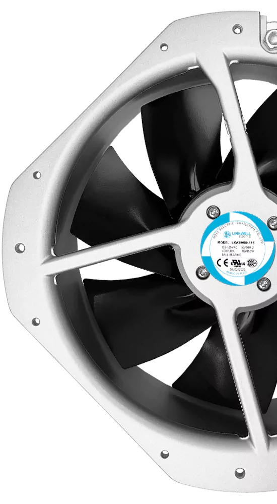
In a multi-fan enclosure, one stopped fan is not always just “zero airflow.” Its opening can become a low-resistance leak. The remaining fans pressurize one side of the panel, and some of their airflow returns through the failed fan instead of passing through the equipment.
The stopped impeller may rotate backward in that stream. This is windmilling. It can reduce useful system airflow, complicate restart and make a simple tachometer signal look healthier than the failed cooling channel really is.
What Causes Reverse Airflow Through a Failed Fan?
Backflow needs a pressure difference and an open path. In a parallel fan bank, the running fans raise pressure in the common discharge plenum. If the stopped fan connects that plenum back to the inlet side, air can move through it in reverse.
The amount depends on the failed fan’s reverse-flow resistance, the common plenum, grille and duct losses, and the operating point of the remaining fans. A free-spinning impeller may offer less resistance than a locked rotor, but neither condition should be assumed without a test.
Backflow can also occur when an external wind, buoyancy or another blower creates pressure across an idle fan. This is why the topic matters beyond large HVAC arrays; compact cooling fans in power electronics, telecom shelves and control cabinets can share the same failure mechanism.
Backflow, Windmilling and Reverse-Powered Operation
| Condition | What happens | Main concern |
|---|---|---|
| Backflow | Air moves opposite the intended direction through the stopped fan | Loss of useful system airflow |
| Windmilling | The reverse air stream rotates the impeller | Alarm ambiguity, restart load and mechanical behavior |
| Commanded reverse operation | A motor and impeller are intentionally driven in reverse | Different from passive backflow; performance may be poor unless designed for it |
Do not assume that reversing supply polarity will make a brushless DC fan operate backward. Its electronics and blade geometry are designed for a specified direction. Passive windmilling is an aerodynamic response, not a supported reverse operating mode.
Why Backflow Can Defeat N+1 Redundancy
An N+1 design is supposed to maintain the required cooling after one fan fails. That calculation is incomplete if it treats the failed position as a sealed plate. In reality, the opening may return part of the surviving fans’ flow to the inlet side.
The result is a double penalty: one fan’s forward contribution disappears, and some output from the remaining fans is lost through the failed branch. System pressure also changes, so each surviving fan moves to a new point on its curve. The article on fan redundancy and failure testing explains why a real one-fan-out test is essential.
Note: “N+1 fans installed” does not prove N+1 cooling. The system must meet the thermal requirement with one fan stopped, the failed opening in its real state, and the filter at its allowed service condition.
Can Windmilling Create a False Tachometer Signal?
Possibly. An FG or tachometer output is generated according to the fan’s internal design. Some fans may produce pulses while the rotor is being driven by external airflow; others may not, and reverse rotation may be handled differently. A controller that treats any pulse as proof of healthy cooling can therefore make the wrong decision.
Use a fault strategy that considers commanded state, rotation direction if available, expected RPM range and temperature or airflow response. An RD alarm signal may provide a clearer locked-rotor indication, but its behavior must also be confirmed for the exact model. See how the fan tachometer signal works.
What Happens When a Windmilling Fan Restarts?
A motor starting from reverse rotation may need to decelerate the rotor, stop it and accelerate in the intended direction. That transient can differ from a normal start from rest. The control electronics may wait, retry, current-limit or enter protection depending on the model.
Do not assume that auto-restart or locked-rotor protection covers every windmilling condition. If restart after a fan or power-channel recovery is part of the equipment safety case, test it across the expected reverse speed, supply range and temperature.
Ways to Reduce Reverse Airflow
Backdraft damper or check flap. A passive flap can close the failed branch, but it adds pressure drop during normal operation and may chatter or fail to open at low fan pressure.
Isolation shutter or controlled damper. An active device can provide better sealing, but adds control logic, failure modes, space and maintenance.
Fan placement and plenum design. Increasing branch resistance or separating flow paths can reduce backflow without a moving damper. The effect must be balanced against normal pressure loss.
Control coordination. Starting and stopping fans together may reduce temporary reverse rotation, but it does not solve a permanent failed-fan opening.
Any damper or grille must be included in the fan curve and noise evaluation. A compact axial fan may not have enough pressure margin to tolerate a heavy flap designed for a larger blower.
How to Test a One-Fan-Failed Condition
- Operate the equipment at maximum thermal load and worst expected ambient temperature.
- Use production filters, guards, doors and cable routing.
- Stop one fan electrically without blocking its opening unless the design includes a closure device.
- Observe airflow direction through the failed position and record any windmilling RPM.
- Measure surviving-fan RPM, current, airflow or pressure, and critical component temperatures.
- Restore the failed channel and verify a reliable restart.
- Repeat for each fan position if the plenum is not symmetric.
Keep hands and instruments clear of an impeller that may start unexpectedly. Use guards and a controlled fault injection method. For electrical safety, follow the equipment’s lockout and test procedure.
Choosing Fans and Controls for a Redundant System
Share the array layout, common plenum, number of fans, required one-fan-out airflow, fan signal requirements and expected failure response with LINKWELL. The review should include the fan curve, tachometer or alarm behavior, startup current and the pressure loss of any isolation device.
The parallel-fan operating point is covered in fans in parallel versus series. Redundancy should be judged by the complete system, not by multiplying a free-air CFM value by the number of fans.
Frequently Asked Questions
Can air flow backward through a stopped axial fan?
Yes. If pressure is higher on its outlet side, the stopped fan opening can pass reverse flow.
Is windmilling harmful to a cooling fan?
It may affect alarms and restart behavior. Mechanical and electrical consequences depend on the model and reverse speed, so test the actual fan.
Will an FG signal detect a failed fan?
It can detect missing or abnormal rotation, but external airflow may spin the rotor. The controller should validate RPM against the commanded state and cooling result.
Does a backdraft damper always solve the problem?
No. It reduces reverse flow only if it seals reliably, and it adds normal pressure drop. Low-pressure compact fans may require a very light, carefully tested device.
How should N+1 cooling be verified?
Stop one fan in the installed system and measure airflow, pressure and component temperatures with the failed opening left in its real condition.