
Your controller says the fan is running, but the enclosure temperature keeps climbing. Or the fan spins normally while the PLC reports zero RPM. In both cases, the problem may not be the motor itself. It may be the way the fan tachometer signal is specified, wired or interpreted.
A tachometer output gives the host controller a pulse train related to rotational speed. It is commonly called FG, TACH or speed feedback. Used correctly, it lets your equipment confirm that a cooling fan is rotating, detect a speed drop and record a developing airflow problem before an overtemperature shutdown occurs.
The signal is not universal, however. Connector colors, pulse count, output circuit and electrical limits can differ between fan models. A safe design starts with the exact fan drawing rather than a generic pinout found online.
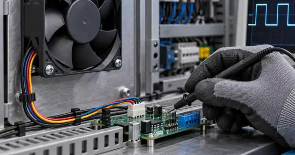
What a fan tachometer signal actually tells you
An FG output reports rotor movement. A sensor and switching circuit inside the fan produce pulses as the rotor turns. The host counts those pulses during a known time interval and converts the frequency into revolutions per minute.
This is valuable in control cabinets, telecom equipment, inverters, UPS systems, energy storage equipment and other machines where loss of cooling can damage electronics. The controller can use the signal to:
- display or log fan speed;
- detect a stopped fan;
- identify a gradual speed reduction;
- compare commanded speed with actual speed; and
- trigger an alarm, speed increase or controlled shutdown.
Rotation feedback does not measure airflow. A fan may produce normal tachometer pulses while a filter is blocked, a grille is covered or the impeller is turning in recirculating air. Treat FG as one part of cooling-system monitoring, not proof that the required airflow is reaching the components.
FG, PWM and RD are different signals
| Signal | Direction | Main purpose | What it cannot prove |
|---|---|---|---|
| FG or TACH | Fan to controller | Reports rotational pulses for speed calculation | Actual airflow or cooling capacity |
| PWM | Controller to fan | Commands a speed or duty level on compatible models | That the fan reached the requested speed |
| RD or alarm | Fan to controller | Changes state when a defined rotation fault occurs | Continuous RPM |
A PWM command and an FG signal are often used together. The controller requests a speed through PWM and checks the result through FG. An RD output is simpler when the equipment only needs a normal/fault indication.
Do not assume every three-wire or four-wire industrial fan follows a PC connector convention. LINKWELL DC and EC fan options can include speed control and monitoring functions, but the wire assignment and signal characteristics must be confirmed for the selected model and order code.
How RPM is calculated from FG pulses
The calculation needs two values: measured pulse frequency and pulses per revolution, usually abbreviated PPR.
Fan speed (RPM) = FG frequency (Hz) x 60 / pulses per revolution
Suppose the controller measures 100 Hz and the fan specification states two pulses per revolution:
Fan speed = 100 x 60 / 2 = 3,000 RPM
Two pulses per revolution is common in some four-wire cooling fan interfaces, but it must not be assumed for every industrial fan. Different sensor and motor designs can produce different pulse counts, so the PPR value must come from the drawing or specification for the exact fan model.
Note: If the controller uses the wrong PPR value, the displayed speed can be exactly one-half, twice or another fixed multiple of the real RPM. Check PPR before treating the reading as a mechanical fault.
Check the electrical output before connecting it
Many fan tachometer outputs are open-collector or open-drain outputs. Such an output pulls the signal toward ground but does not create its own high level. The host circuit supplies the high level through a pull-up resistor.
That does not mean one pull-up voltage or resistor value fits every fan. The allowable pull-up voltage, sink current, low-level voltage and leakage current are model-specific. Some outputs are internally pulled up, some need an external supply, and isolated AC-fan sensor circuits may use a different reference arrangement.
Before wiring, confirm:
- the signal type and logic polarity;
- maximum pull-up voltage and sink current;
- recommended pull-up resistance, if specified;
- whether fan ground and controller ground must be common;
- PPR and expected frequency range;
- connector pinout and wire colors; and
- behavior during startup, low-speed operation and locked rotor.
These limits belong to the exact fan output circuit, not to the term FG alone. Confirm the pull-up voltage, sink current, logic levels and reference-ground arrangement on the model drawing before connecting the signal to a controller.
A practical wiring and commissioning sequence
Confirm the exact order code
Two fans with the same frame size and voltage may have different lead functions. One version may provide FG, another RD, and another only power leads. Ask for the wiring drawing that matches the sample and production order.
Power the fan correctly first
Verify supply voltage, polarity and available startup current before diagnosing the signal. A fan that repeatedly resets because of supply collapse can produce an intermittent FG waveform that looks like a sensor problem.
Verify the signal with an oscilloscope
Measure the FG line at the controller input. Check the low and high levels, pulse frequency, edge quality and noise. A multimeter may show an average voltage but cannot reliably reveal missing pulses or slow edges.
Compare calculated RPM with an independent measurement
A non-contact tachometer can provide a useful commissioning cross-check. Exact agreement is not expected from every handheld method, but a large fixed ratio usually points to an incorrect PPR setting.
Test the complete operating range
Check full speed, minimum commanded speed, startup and expected temperature-control transitions. At very low speed, a short sampling window may contain too few pulses for a stable reading. The controller may need a longer averaging period without delaying real fault detection excessively.
Why a fan can spin while the controller reports zero RPM
| Observed behavior | Likely cause | First check |
|---|---|---|
| Fan runs, FG stays low | Missing pull-up, wrong pin or short to ground | Verify output circuit and connector pinout |
| Fan runs, FG stays high | Open signal wire, no common reference or incompatible input | Check continuity and ground arrangement |
| RPM is exactly half or double | Incorrect pulses-per-revolution setting | Compare controller configuration with fan specification |
| RPM jumps randomly | Electrical noise, weak pull-up or long unshielded routing | Inspect waveform at the receiving input |
| Alarm appears only at low speed | Threshold or sampling window is unsuitable | Review the minimum-speed logic and timing |
| Signal disappears during startup | Supply voltage collapses or startup blanking is too short | Measure fan voltage and current during startup |
Route the signal away from switching power conductors where practical, especially near variable-frequency drives, contactors and high-current DC cables. If the equipment environment is electrically noisy, validate the complete harness length and controller input instead of testing with a short bench lead only.
Set alarms around cooling risk, not a perfect RPM number
A useful threshold allows for normal speed tolerance, supply variation, command changes and measurement resolution. If the limit sits too close to nominal speed, normal variation creates nuisance alarms. If it is too low, the system may miss bearing wear, obstruction or a failing supply until airflow is already inadequate.
Use different logic for startup and steady operation. The fan needs time to accelerate, and some sensor functions intentionally delay their response. A practical controller may apply startup blanking, then compare speed against a threshold related to the current command.
For variable-speed fans, a single fixed minimum RPM may be inappropriate. One approach is to create an acceptable speed band for each command range. The final safety logic should still be confirmed through thermal testing because speed and cooling are not identical.
Specify the feedback function with the fan
When requesting a LINKWELL fan with tachometer feedback, provide more than the voltage and frame size. Include the controller input voltage, preferred signal type, required PPR, cable length, connector, speed range, PWM or analog-control method and desired failure response.
Also state how the equipment will react to loss of feedback. A telecom unit may raise a maintenance alarm, while a high-power inverter may need to reduce load. That system-level decision affects the threshold, response time and redundancy strategy.
For related integration details, see EC fan wiring, EC fan speed control and fan redundancy design.
Frequently asked questions
Is FG the same as a fan tachometer signal?
Usually, yes. FG means frequency generator and is widely used for a pulsed speed-feedback output. TACH is another common label. Confirm the model drawing because naming alone does not define the electrical limits.
Does a tachometer signal control fan speed?
No. It reports rotational speed. PWM, analog voltage or another control input commands speed on a compatible fan.
Does every fan produce two pulses per revolution?
No. Two PPR is common, especially in standardized four-wire interfaces, but industrial fans may differ. Use the value stated for the exact model.
Can FG detect a blocked filter?
Not directly. The fan may maintain normal RPM while airflow falls because system resistance increased. Combine speed monitoring with temperature, pressure or maintenance checks when a blocked filter is a critical risk.
Can an FG wire connect directly to a PLC input?
Only if the voltage, current, switching frequency, logic polarity and isolation requirements are compatible. An interface circuit may be required. Review both the fan output specification and PLC input specification.
Why does the RPM reading fluctuate at low speed?
The controller may receive too few pulses during a short sampling window, or the signal edges may be noisy. Check the waveform, PPR setting, pull-up arrangement and averaging time before changing the fan.

