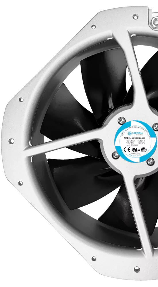
A cooling fan burn-in test operates a fan for a defined period under controlled conditions to screen early failures or unstable units. It can reveal startup problems, abnormal current, noise, vibration, speed drift or signal faults. It cannot, by itself, prove the fan’s service life or predict field reliability.
The value of burn-in comes from a clear purpose and a controlled process. “Run the fan for 24 hours” is not a complete test specification. Voltage, temperature, mounting, airflow restriction, sample plan, measurements and pass/fail limits determine what the result actually means.
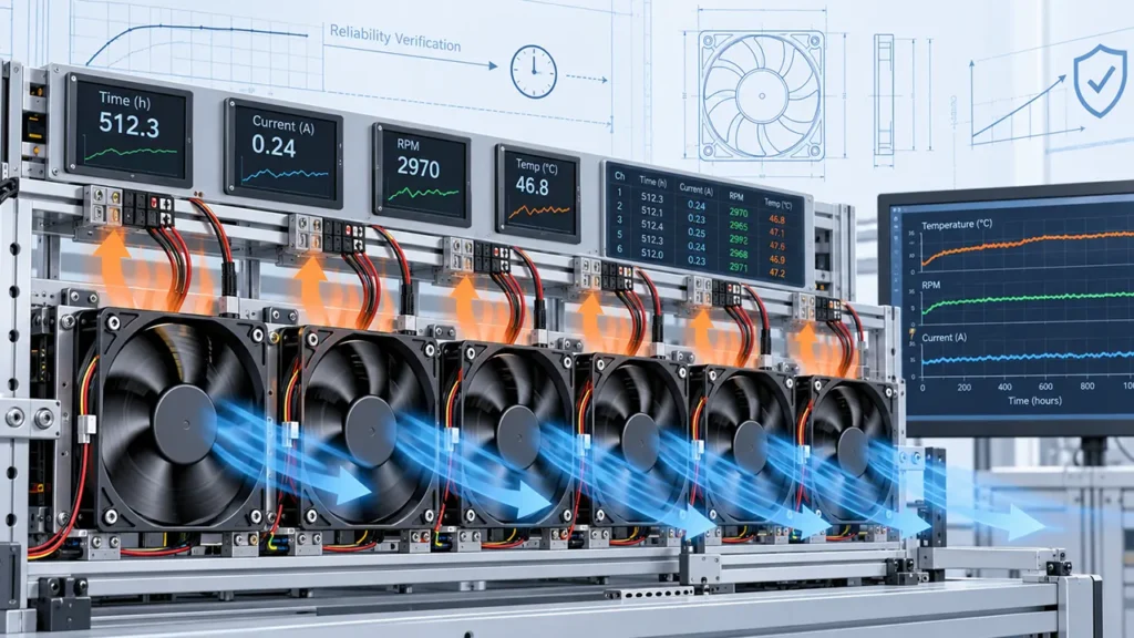
What Is a Cooling Fan Burn-In Test?
Burn-in is a screening activity. Fans are operated so defects that would otherwise appear shortly after installation have a chance to become visible before shipment or equipment assembly. The process may be applied to engineering samples, a production lot or every unit, depending on product risk and the agreed quality plan.
The test is most useful when it targets known early-life failure mechanisms and records measurable changes. Simply accumulating running time without monitoring or defined acceptance criteria can create cost and delay without providing reliable evidence.
Reliability stress screening is a broader discipline than fan burn-in. IEC 61163-2 provides guidance on reliability stress-screening techniques for electrical, electronic and mechanical components, while also making clear that a general guidance document is not a ready-made test plan for every component. A fan program still needs model-specific conditions and limits.
What Problems Can Burn-In Find?
A well-designed burn-in can expose defects that appear when the fan starts, warms up and operates continuously. Examples include:
- Failure to start or delayed startup
- Intermittent electrical contact or lead connection
- Abnormal running current
- Unstable speed or repeated restart behavior
- Unusual bearing, motor or aerodynamic noise
- Excessive vibration
- FG, tachometer, RD or alarm-signal faults
- Temperature-sensitive electronic defects
- Assembly interference that appears after thermal expansion
Burn-in is less effective when the stress does not activate the suspected failure mechanism. A room-temperature, free-air test may not reveal a connector problem triggered by vibration, a low-temperature starting problem or overheating that occurs only behind a restrictive filter.
What Burn-In Cannot Prove
Passing burn-in does not establish that a fan will reach a particular operating life. Service life depends on bearing construction, lubricant, temperature, speed, dust, humidity, orientation, electrical stress and the equipment’s duty cycle. A short test cannot reproduce every field condition.
Burn-in also cannot:
- Replace a statistically planned life or endurance test
- Prove an L10 life or MTBF claim
- Validate every mounting orientation and system restriction
- Demonstrate resistance to humidity, condensation, salt or chemicals unless those conditions are included
- Guarantee that a production process will remain controlled after the tested lot
- Correct a weak design or an incompatible application
Note: A fan that survives burn-in has passed the defined screening conditions. It has not automatically passed all service-life, environmental or equipment-level requirements.
Burn-In vs Endurance, Life and Qualification Testing
| Test type | Main purpose | Typical question answered |
|---|---|---|
| Burn-in or screening | Detect early failures or unstable units | Does this unit meet the screening limits after controlled operation? |
| Endurance test | Observe performance over extended operation | How does the fan change under a defined long-duration condition? |
| Life test | Estimate or demonstrate life using a defined statistical and engineering method | What life claim is supported under stated conditions? |
| Qualification test | Show that a design meets specified electrical, mechanical and environmental requirements | Is the design suitable for the stated application and test plan? |
| Installed equipment validation | Confirm performance in the final product | Does the complete equipment cool, control and detect faults correctly? |
These activities may share equipment and measurements, but they should not be reported as if they are interchangeable. For example, a burn-in station may collect speed and current data that later helps reliability analysis, yet the screening result alone still does not establish a life distribution.
For terminology related to fan-life claims, see Fan L10 Life vs MTBF.
Define the Purpose Before Choosing Test Conditions
A useful test plan begins with the reason for testing. Is the goal to screen unstable startup, check a new motor-control board, detect assembly noise, verify an alarm signal or reduce early field returns? Different goals require different conditions.
If the observed field problem occurs after a cold start, a continuously running warm test may miss it. If the failure occurs behind a loaded filter, free-air operation may not reproduce the motor temperature. If the issue is intermittent wiring, repeated start-stop cycles or controlled movement may be more revealing than one uninterrupted run.
Write the suspected failure mode next to the selected stress and measurement. If there is no credible connection between them, reconsider the test.
Key Burn-In Test Conditions
Supply Voltage
Use a controlled supply and record voltage at the fan terminals, not only at the power supply. Cable and connector voltage drop can change startup and speed. The test plan should state whether the fan runs at rated voltage, a permitted limit or several points within the specified operating range.
Do not apply an overvoltage stress without a justified method and model-specific limit. A stress that creates a new failure mechanism may reject acceptable fans without predicting field behavior.
Temperature
Temperature affects electronics, bearings, lubricant, winding resistance and airflow density. Record the ambient near the fan and, when relevant, the temperature of the fan frame or motor area. If elevated temperature is used, define how it relates to the intended environment and which fan temperature is being controlled.
A semiconductor high-temperature operating-life test is not automatically a fan burn-in procedure. Standards such as IEC 60749-23 illustrate how electrical bias, temperature, duration and purpose must be defined for a specific component category. A complete fan adds bearings, rotor dynamics, airflow and mechanical assembly, so its method must address the entire fan.
Mounting and Orientation
A fan resting loosely on a bench may sound and vibrate differently from a fan clamped into its equipment. Specify orientation, fasteners, guard, shroud and mounting surface. If the fan can be installed in multiple orientations, decide whether one represents the worst relevant condition or whether more than one requires validation.
Airflow Restriction
Free-air operation is easy to reproduce but may not represent the motor load or cooling of the installed fan. A restriction fixture can be used when the real application has a filter, heat exchanger or dense air path. The fixture must be controlled and documented so different lots are compared under the same condition.
Duty Cycle and Start-Stop Pattern
Continuous operation stresses different features from repeated starting. If the product frequently cycles, define on-time, off-time, number of starts and the temperature at restart. For PWM fans, state the control frequency, duty cycle, minimum command and whether the supply remains continuously applied.
Duration
There is no universal burn-in duration suitable for every fan. The chosen time should be supported by defect history, process capability, customer requirements or a screening study. Longer is not automatically better. Excessive screening consumes fan life, energy and production capacity and can add handling damage.
What to Measure During Burn-In
A pass/fail light shows only that power is present. A stronger process records the variables related to the target failure mode.
| Measurement | What it can reveal | Important control |
|---|---|---|
| Startup result and time | Failure to start, delay or repeated restart | Terminal voltage, command and starting temperature |
| Running current | Electrical or mechanical abnormality and drift | Voltage, temperature, speed command and restriction |
| Speed or FG frequency | Speed instability, loss of rotation or signal problems | Pulse interpretation, command and measurement interval |
| RD or alarm output | Fault-detection operation | Logic level, pull-up and fault timing |
| Noise | Bearing, commutation, resonance or rubbing symptoms | Background noise, mounting and listening distance |
| Vibration | Imbalance, looseness or structural interaction | Sensor location, mounting stiffness and speed |
| Temperature | Unexpected heating or unstable operation | Probe position, ambient and airflow condition |
Measurements taken only at the end can miss an intermittent event. Automated logging is useful when the process needs to catch short speed drops, current excursions or alarm transitions. The logging rate should be fast enough for the event being investigated without producing unmanageable data.
Set Acceptance Criteria Before the Test Starts
Acceptance criteria should come from the approved fan specification and the purpose of the test. They may include successful startup, current range, speed tolerance, stable feedback, no persistent alarm, acceptable noise and no visible damage.
Avoid vague criteria such as “sounds normal” unless a controlled reference and trained inspection method are defined. Also avoid changing limits after seeing the data. If an unexpected pattern appears, document it as an investigation rather than silently redefining pass and fail.
Consider both absolute limits and change from the initial measurement. A fan can remain inside a broad specification while showing a significant shift that deserves review. Conversely, a small measurement change may be normal instrument variation. Gauge capability and repeatability are part of a credible test.
Sample Burn-In and 100 Percent Screening
Sample burn-in evaluates selected units from a lot or process. It is less expensive and can support process monitoring, but a passing sample does not prove that every unit is free of an individual assembly defect.
One hundred percent screening exposes every production unit to the defined process. It may be justified when early failures have high consequences or when a known defect can be screened effectively. It also adds equipment, handling, traceability and capacity requirements.
The decision should consider field risk, production volume, defect mechanism, historical data and whether the screen itself can damage good units. A customer requirement for “burn-in” should be converted into a written test condition and sampling rule before quotation and production.
Traceability and Test Records
A burn-in result is useful only when it can be connected to the tested fan and the test conditions. Record the model, revision, lot or date code, sample identity, test station, fixture, start and finish time, voltage, temperature, control settings, measurements, failures and disposition.
When a unit fails, preserve the condition long enough to investigate it. Repeatedly restarting, disassembling or swapping parts without a record can destroy evidence. Separate the failure symptom from the suspected cause until analysis confirms the mechanism.
Common Burn-In Mistakes
- Choosing a duration without defining the screening objective
- Recording power-on time but not voltage, temperature or fan identity
- Testing only in free air when the field problem occurs under restriction
- Running continuously when the suspected failure happens at startup
- Using excessive temperature or voltage without a justified acceleration model
- Calling a short screening test a life test
- Checking rotation but ignoring speed, current, signals, noise and vibration
- Changing acceptance limits after the test
- Failing to analyze rejected units and improve the upstream process
How Burn-In Fits Into OEM Fan Validation
Burn-in is one layer of evidence. Before production, the OEM should also confirm mechanical fit, airflow and static pressure, voltage range, startup current, PWM response, FG or RD behavior, temperature, noise, vibration and environmental requirements in the final equipment.
The existing Cooling Fan Prototype Validation Before Mass Production guide covers design approval, while How to Test a Cooling Fan explains basic functional checks. Burn-in should not repeat those activities without a defined screening purpose.
After production begins, screening data can reveal trends. A gradual change in current, speed, noise rejection or failure location may indicate tool wear, material variation, assembly drift or a test-station problem. The quality team should review the trend rather than treating every passing unit as independent evidence.
Information to Agree With the Fan Supplier
If burn-in is required for a LINKWELL fan project, define the model and revision, quantity or sampling plan, voltage, temperature, orientation, airflow condition, speed command, duration, start-stop pattern, measurements, acceptance criteria, traceability and report format.
Also define who owns failed-unit analysis and whether screened products can be shipped after the test. Requirements should be agreed before mass production because burn-in can affect lead time, fixture capacity, handling and cost.
Frequently Asked Questions
How long should a cooling fan burn-in test last?
There is no universal duration. The time should be based on the screening objective, known failure mechanism, process history, application risk and agreed customer requirement. A longer test is not automatically more predictive.
Does burn-in reduce early fan failures?
It can screen defects that become visible under the chosen conditions. It does not remove the root cause. Failure analysis and process correction are still required if screening finds repeated problems.
Is burn-in the same as a fan life test?
No. Burn-in is normally a relatively short screen for early failures. A life test uses defined conditions, failure criteria, sample size and analysis to support a life or reliability conclusion.
Should every cooling fan receive burn-in?
Not necessarily. The decision depends on application risk, defect history, production controls, customer requirements and whether the screen can detect the relevant failures efficiently.
Can burn-in be performed at high temperature?
Yes, when elevated temperature is justified, controlled and within an approved method. The test must avoid creating unrealistic failure mechanisms, and the result must not be interpreted beyond the defined condition.
What data should be recorded during fan burn-in?
Record fan identity, lot, voltage, temperature, mounting, restriction, control command, duration, startup behavior, current, speed or feedback, alarm state, noise, vibration, failures and final disposition.