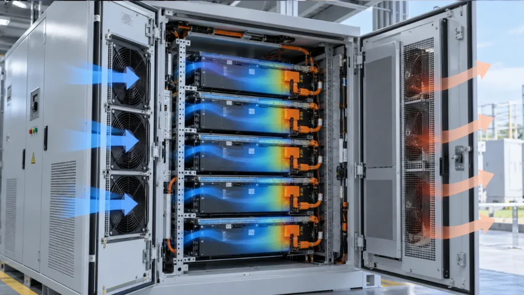
A battery cabinet can have an acceptable average temperature while one rack level or module remains significantly warmer. Increasing total fan airflow does not necessarily correct that imbalance if most of the extra air follows an easier route around the batteries.
Battery cabinet temperature uniformity depends on heat generation, inlet-air conditions and how airflow is distributed through the modules. Fan selection must therefore support both heat removal and balanced delivery to the least-cooled region.
Define Which Temperatures Need to Be Uniform
A cabinet-air sensor, a module-surface probe and a cell sensor report different conditions. Before setting a uniformity target, identify the measurement level: cell to cell, within a module, between modules, between rack levels or across the full cabinet.
A useful measured spread is:
Temperature spread = highest measured temperature – lowest measured temperature
The sensors must refer to the same operating period and a defined comparable location. Do not compare one module’s hottest surface with another module’s inlet air and call the difference cell uniformity.
Use the battery and equipment supplier’s limits for maximum temperature, allowed spread and charge/discharge conditions. No single temperature band or maximum difference applies to all chemistries and cabinet designs.
Why Average Cabinet Temperature Can Mislead
Air follows pressure differences and available passages. Wide gaps, open ends and short paths may carry more flow than narrow module channels. A return-air sensor blends those streams and can hide a poorly cooled module.
Heat generation is also uneven. Electrical duty, state of charge, cell condition, connections and module construction can change local losses. A warm region may have insufficient cooling, greater heat generation or both.
Start by mapping the pattern. If the same position stays hot after load and sensing are verified, investigate its airflow. If the hot location follows a particular module, the battery or electrical condition may require investigation rather than a cabinet airflow change.
Common Causes of BESS Cabinet Hot Spots
| Cause | Typical effect | Check |
|---|---|---|
| Air bypass around modules | High cabinet flow with weak cooling through the intended channels | Gaps, blanking panels, seals and module interfaces |
| Unequal branch resistance | Some rack levels receive less flow | Plenum geometry, outlet area and branch pressure |
| Warm-air recirculation | Selected modules receive preheated inlet air | Supply-return separation and leakage |
| Serial heating along an air path | Downstream modules see warmer air | Path length, module sequence and supply arrangement |
| Filter or coil loading | Reduced total flow and altered distribution | Pressure drop and maintenance condition |
| Unequal heat generation | Hot regions persist despite adequate local flow | Electrical losses and battery diagnostics |
Build the Air Path Around the Modules
Give cooling air a clear route from the supply plenum, through the intended module passages and back to the return. Gaps beside racks or around cable bundles can let air bypass the batteries, leaving some modules warm even when total cabinet airflow appears adequate.
Use blanking panels, shrouds and seals where they help close these shortcuts. Keep required service clearances accessible, and check that cables do not obstruct module inlets. After changing the layout, reassess system resistance and the fan operating point—the same fan may deliver a different airflow through the revised cabinet.
Channel size also needs care. A narrower passage can increase local air velocity, but the added pressure drop may reduce flow through that branch. A wider passage can lower resistance while allowing air to miss the surfaces that need cooling. Evaluate these changes across the complete cabinet rather than choosing a gap from velocity alone.
Validate the layout by comparing module inlet temperatures, branch airflow or pressure, and temperatures at the least-cooled locations. If one rack level remains warmer, check for bypass, recirculation or unequal branch resistance before increasing fan speed.
Balance Airflow Between Rack Levels
A supply plenum does not automatically deliver the same flow to every outlet. Pressure varies along the plenum, while each branch has its own resistance. Modules closest to a fan are not necessarily the only ones receiving excess flow; the pattern depends on the complete arrangement.
Measure branch flow or representative pressure differences before adding restrictions. Baffles, outlet adjustments or revised manifold geometry can improve distribution, but closing a well-cooled branch without checking the fan curve can reduce total capacity.
Where CFD is used, validate the baseline against measured pressure, airflow and temperatures. Include realistic fan curves, leakage, heat sources and boundary conditions. A visually smooth streamline plot is not evidence that every module receives sufficient cooling.
Select Fans at the Installed Operating Point
The required fan must provide useful airflow against module channels, grilles, filters, coils and ducts. Free-air CFM alone does not establish suitability.
Axial fans can fit relatively straight paths with suitable resistance. Centrifugal options may fit compact ducts, side outlets or higher-pressure requirements. Select according to the required operating point, available space, noise and power budget rather than the fan category alone.
Multiple fans share a system and influence each other’s operating points. Their free-air ratings cannot simply be added as guaranteed cabinet flow. If redundancy is required, evaluate how a failed fan opening affects backflow and the remaining airflow distribution.
See How to Read a Fan Curve and Fan Redundancy for these selection checks.
Cabinet Air Temperature Still Needs a Heat-Rejection Path
Balanced internal airflow cannot remove unlimited heat. An open-loop cabinet depends on acceptable outside air and sufficient temperature difference. A sealed cabinet needs walls, a heat exchanger or an active cooling system to reject the losses.
Air conditioning or another cooling device can supply cooler air while internal DC or centrifugal fans distribute it. These functions must be coordinated. A circulation fan cannot compensate for inadequate cooling capacity, and an oversized cooler cannot fix every blocked module path.
For a wider system overview, see Energy Storage Systems Cooling.
Control for Both Maximum Temperature and Spread
A control strategy based only on average return temperature can overlook a hot module. Evaluate the highest relevant battery temperature, measured spread, inlet condition and BMS operating limits.
Higher fan speed may improve convection, but it can offer diminishing benefit if distribution remains poor. Very low speed can expose differences between parallel branches or cause unreliable restart on an incompatible fan/controller combination.
Verify PWM behavior, minimum speed, startup and FG or RD feedback for the exact model. These signals can reveal fan operation, but a rotating fan does not prove that a branch is unobstructed.
A Validation Plan for Temperature Uniformity
- Define maximum temperature, allowed spread and measurement locations from the approved battery requirements.
- Establish electrical duty, initial state of charge, ambient and supply-air conditions.
- Map representative module inlets, outlets, surfaces and available BMS temperatures.
- Record branch airflow or pressure, fan speed, control command and cooling-unit state.
- Run representative charge and discharge profiles long enough to observe the relevant thermal response.
- Repeat with credible filter loading, ambient extremes and configuration variations.
- Assess approved cooling-fault scenarios and verify alarm and protective response.
Compare configurations under equivalent conditions. A lower final temperature is not evidence of an improved air path if the second test used lower current, cooler inlet air or a different initial state.
Account for sensor accuracy and repeatability. If the measured change is similar to the uncertainty of the instruments, report the limitation before claiming a uniformity improvement.
Normal Cooling and Thermal Runaway Are Separate Functions
This article addresses heat removal during normal operation. An ordinary circulation fan is not a thermal-runaway suppression or emergency smoke-control system.
Battery abuse, off-gassing or runaway events require the equipment’s hazard analysis and specified emergency response. Ventilation during those events must follow that design; improvised fan operation can move gases or heat into unintended areas.
Note: Do not test battery fault conditions by blocking cooling or defeating BMS protection without an approved test procedure and suitable facility. Routine fan selection does not establish emergency-event capability.
Information Needed for OEM Fan Selection
Provide cabinet and module drawings, heat losses over the duty cycle, inlet temperature range, required temperature limits, branch restrictions, leakage assumptions, fan space, supply range and required monitoring.
For LINKWELL’s new energy applications, DC, EC or centrifugal fan candidates can be reviewed against the defined system. Environmental, control and protection options require confirmation for each model, followed by cabinet-level validation.
Frequently Asked Questions
What is a good temperature difference in a battery cabinet?
Use the battery supplier’s approved limits for the chemistry, module and operating condition. Specify where and when temperatures are measured before defining an acceptable spread.
Will more airflow always improve uniformity?
No. Extra flow may follow bypass paths. Distribution, module resistance and heat-generation differences can matter more than the total airflow.
Should a BESS cabinet use axial or centrifugal fans?
Select from the required airflow and static pressure, outlet geometry, space and control requirements. Either can be suitable in an appropriately designed air path.
Can one cabinet sensor prove uniform battery cooling?
No. A blended air measurement can hide a local hot spot. Validate representative modules and rack levels alongside the available BMS measurements.
Can ordinary cooling fans stop thermal runaway?
No such capability should be assumed. Normal cooling fans must not be presented as a replacement for the battery system’s dedicated safety design and emergency response.