
A cooling fan runs normally from a bench supply, but the finished equipment resets when several fans start together. Another system blows a fuse only at power-on even though steady current is comfortably below the fuse rating. Both problems point to the same missing design input: cooling fan startup current.
The current printed on a fan label usually describes rated or nominal operation. It may not show the brief power-on inrush, the current required while the rotor accelerates or the behavior of the fan’s protection circuit. Those events can be short, but they are long enough to pull down an undersized supply, trip electronic current limiting or create intermittent startup faults.
There is no reliable universal multiplier for every AC, DC and EC fan. The peak and duration depend on the motor, internal electronics, impeller inertia, supply impedance, applied voltage and starting condition. Use model-specific data and verify the assembled equipment.
Inrush current and startup current are not always the same event
The terms are often used interchangeably, but separating them helps you choose the right measurement and protection.
| Current event | What causes it | Typical design concern |
|---|---|---|
| Power-on inrush | Charging internal capacitors and energizing the drive circuit | Very short peak affecting fuses, breakers or electronic current limiting |
| Motor startup current | Torque demand while the rotor accelerates and back EMF builds | Longer pulse causing supply sag or failed acceleration |
| Steady operating current | Normal motor, bearing, aerodynamic and electronic load | Continuous power and thermal sizing |
| Locked-rotor current behavior | Rotor obstruction and repeated protection attempts | Heating, repeated supply loading and fault response |
A typical startup waveform may contain a brief capacitor-charging inrush followed by a broader acceleration current that falls as rotational speed and back EMF increase. The two events place different demands on fuses, electronic current limiting and the power supply, so peak amplitude and duration should be checked separately for the selected fan.
EC fans contain electronic power conversion and can produce a very short capacitor-charging peak even when running power is low. DC brushless fans also contain commutation electronics and may show both a narrow inrush spike and a broader acceleration current. Traditional AC fan behavior depends on motor construction and protection method.
Why the fan starts on the bench but fails in the machine
A laboratory supply may have short leads and generous peak-current capability. The production machine may add a smaller power supply, long harness, connector resistance, shared loads and a controller that turns every fan on at once.
During startup, voltage at the fan terminals can fall below the fan’s operating or restart requirement. The fan controller resets, current drops, the supply recovers and the fan tries again. This cycle may sound like clicking or repeated speed surges. An FG signal may also appear and disappear, misleading a technician into suspecting the tachometer circuit.
Other symptoms include PLC or communication-module resets, a fuse opening despite acceptable running current, one fan starting while another remains stopped, repeated EC fan initialization, relay contact wear and faults that disappear when a stronger bench supply is used.
Do not estimate startup current from rated watts alone
Rated input is needed for continuous sizing, but it cannot reveal the peak waveform.
DC running power (W) = voltage (V) x running current (A)
Total running current = sum of all fan running currents
Startup assessment uses the loads that can start during the same time window:
Required peak current = simultaneous fan startup current + simultaneous non-fan load current
The supply must support that peak for the measured duration while keeping its output within the acceptable voltage range. A supply described as 10 A continuous may have a useful short-duration peak rating, immediate foldback or a hiccup mode that prevents the fan from accelerating.
Note: Do not solve a startup problem by installing a slower fuse without checking conductor protection, connector ratings, applicable safety requirements and actual fault current. Startup coordination and fault protection are separate decisions.
How to measure cooling fan startup current
Measure at the intended supply voltage
Use the lowest and highest normal supply conditions that matter to the design. A fan may draw different current and take longer to accelerate near the low end of its operating range.
Use an instrument fast enough for the event
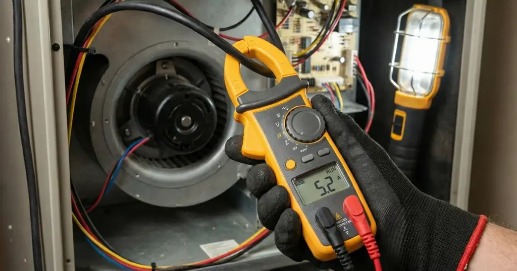
A standard multimeter often averages away a microsecond- or millisecond-scale peak. A current probe and oscilloscope show peak amplitude, duration, repeated attempts and the corresponding terminal voltage. A current shunt can also be used when its resistance, power rating, bandwidth and grounding arrangement are appropriate.
Capture current and voltage together
Record voltage at the fan connector, not only at the power-supply terminals. Long leads and connectors can create a significant difference during the peak.
Use two time scales
A narrow time scale may capture capacitor inrush but miss full rotor acceleration. A wide time scale may hide the initial spike. Take a fast view of power-on and a longer view through stable speed.
Repeat under realistic conditions
Test the intended guard, filter, mounting orientation, air path and cold-start temperature. If the equipment contains several fans, start them with the production sequence instead of measuring each fan in isolation.
How the waveform points to the real fault
| Waveform or symptom | Likely interpretation | Next action |
|---|---|---|
| Very narrow high spike, then normal start | Capacitor-charging inrush | Check fuse, breaker and supply transient response |
| Broad current peak with falling terminal voltage | Supply or wiring cannot support acceleration load | Review supply capacity, cable and connector drop |
| Repeated current pulses with no stable rotation | Supply cycling, obstruction or fan auto-restart behavior | Correlate current, voltage and rotor movement |
| One fan starts late in a group | Unequal branch resistance or current sharing | Measure each fan connector and branch |
| High current remains after the expected start | Mechanical drag, wrong voltage or abnormal motor condition | Stop the test and inspect the model and installation |
Ways to prevent startup-related power trips
Select a supply with documented peak capability
Compare the measured peak current, its duration and repetition rate with the power supply overload curve. A continuous current rating alone is not enough: the supply must keep the fan terminal voltage within its valid range long enough for the rotor to reach stable speed, without entering foldback or repeated hiccup operation.
Reduce voltage drop in the distribution path
Check wire gauge, cable length, connector contacts, PCB traces, relays and fuses. The relevant value is voltage at the fan during startup.
Voltage drop (V) = startup current (A) x total circuit resistance (ohm)
Sequence multiple fans
Staggered starting can reduce simultaneous peak load, provided the equipment remains thermally safe during the delay. The control logic should also define what happens if one fan fails to start.
Use soft-start only when it is compatible
Slowly applying voltage is not safe for every electronically commutated fan. Some fans require a defined supply range and should be speed-controlled through a dedicated input. Use a fan or controller designed for soft starting instead of improvising a voltage ramp.
Coordinate protection
Select branch protection for the conductor, fan circuit and applicable safety standard while allowing normal startup. Validate normal power-on, repeated restart and a genuine electrical fault. A larger fuse is not a substitute for diagnosis.
Locked-rotor behavior belongs in the same review
A fan may cut motor current and retry periodically when the rotor is blocked. Other designs use thermal or impedance protection. The resulting waveform can resemble repeated startup and may keep loading a shared supply.
Protection methods vary with fan construction. Confirm whether the selected LINKWELL model uses current cutoff, automatic restart, thermal protection or another method, then test how the complete equipment responds when the rotor is intentionally prevented from turning under a controlled test condition.
The fan’s internal protection protects the fan; it does not guarantee that the cooled equipment remains safe. Your controller may still need tachometer monitoring, temperature protection, redundancy or controlled load reduction.
What to provide when selecting a LINKWELL fan
For a useful startup-current review, provide the exact fan size and voltage, number of fans, power-supply model, harness length, connector, ambient temperature, startup sequence and controller behavior. State whether PWM, FG or RD functions are required.
Ask for model-specific running current and available startup or inrush data. Then validate the final enclosure. This is more reliable than applying a fixed multiplier to every AC, DC or EC fan.
Related planning guides include cooling fan power consumption, DC axial fan wiring and fan redundancy.
Frequently asked questions
Is fan startup current higher than running current?
It often is, but amplitude and duration depend on the fan design. Some electronic fans have a narrow inrush spike plus a separate acceleration current. Use the exact waveform or manufacturer data.
Can a multimeter measure fan inrush current?
It may capture a slow peak if it has a suitable inrush function, but a normal display often misses short events. An oscilloscope with an appropriate current measurement is better for waveform analysis.
Should I add all fan startup currents together?
Only for fans that can start during the same interval. If the controller sequences them, evaluate each stage and the failure case in which a fan repeatedly retries.
Why does a fan repeatedly start and stop?
Possible causes include supply-voltage collapse, current-limit cycling, a blocked rotor, an incompatible control input or internal auto-restart protection. Measure terminal voltage and current together.
Can a larger capacitor solve the problem?
Sometimes local energy storage reduces a short voltage dip, but it also changes inrush at the upstream supply and switching device. It must be engineered and tested rather than added by trial and error.
Does PWM speed control remove startup current?
Not automatically. Some fans apply a startup routine or minimum speed regardless of requested duty. Confirm the model’s startup behavior and test the actual control sequence.

