
An EC fan can have power at its terminals and still behave in a way you did not expect. It may run at full speed, ignore the controller, stop below a certain command, or repeatedly speed up and slow down. Those symptoms are often blamed on the motor. In practice, the first thing to check is whether the controller, wiring and fan input were designed to work together.
EC means electronically commutated. The motor electronics convert the incoming supply and switch the motor windings internally, so speed can be adjusted without the losses and limitations of many traditional AC fan control methods. That does not mean every EC fan accepts every control signal. A 0-10 V input, a PWM input and a Modbus connection are different interfaces, and even two fans using the same interface may use different thresholds, frequencies or failure settings.
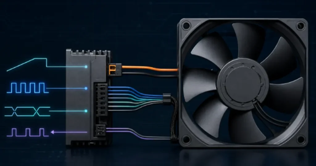
Start with the exact fan interface, not the controller you already have
Before selecting a controller, obtain the connection diagram and control specification for the exact fan model and revision. The product name alone is not enough. You need to confirm the supply voltage, control input type, reference or common terminal, signal limits, minimum speed behavior, feedback outputs and the fan’s response when the signal is lost.
Keep the power circuit and the command circuit separate in your thinking. The power leads supply the fan electronics. The control leads tell those electronics what speed to request. Applying a chopped mains waveform, a generic triac dimmer or an unverified external voltage to the wrong lead can cause poor operation or damage.
Note: Never assume that a label such as 0-10 V defines the full behavior. The datasheet must still state what 0 V means, where the fan starts, whether the input sources or sinks current, and what happens if the wire opens.
Common EC fan speed control methods
0-10 V analog control
A 0-10 V command is popular in ventilation, cooling and building-control systems because it is easy to integrate. In a typical arrangement, a lower command requests a lower speed and a higher command requests a higher speed. The word typical matters. Some fans use a non-zero start threshold, retain a minimum speed, invert the command direction or require a potentiometer connected to a fan-provided reference voltage.
Check these items before wiring:
- Whether the input expects an externally supplied voltage or a resistance connected to an internal reference.
- The permitted voltage range and input impedance.
- Which terminal is signal common and whether it is isolated from power ground.
- The command corresponding to stop, minimum speed and maximum speed.
- Whether an open or shorted input causes stop, minimum speed, maximum speed or an alarm.
Long analog signal cables can pick up electrical noise, especially when routed beside contactors, variable-frequency drives or high-current conductors. Use the cable type, shielding and grounding method specified by the manufacturer. Do not connect shields at both ends automatically; the correct arrangement depends on the equipment grounding design.
PWM control
Pulse-width modulation represents a speed request through duty cycle. For example, the signal may be high for 60 percent of each cycle and low for 40 percent. The fan electronics interpret that duty cycle and set a target speed. The controller is not normally switching the fan’s main power on and off.
Compatibility requires more than matching the letters PWM. Confirm the required signal amplitude, frequency range, polarity, logic thresholds, open-collector or push-pull requirement, common reference and duty-cycle mapping. A controller that produces a 24 V industrial PWM output is not automatically compatible with a fan expecting a lower-level logic input.
PWM can resist some analog-voltage errors, but it is not immune to poor cabling. A missing common, excessive cable capacitance or distorted edges can make the fan read an incorrect duty cycle. If the response is unstable, inspect the waveform at the fan terminals rather than only checking the controller display.
Potentiometer or manual setpoint
A potentiometer is useful when you need a fixed commissioning speed or a simple local adjustment. Many arrangements connect the potentiometer between a fan-provided reference, control input and common. The resistance range and terminal order must match the wiring diagram.
Manual control is simple, but it does not compensate for a clogged filter, changing heat load or a failed fan. If the system must hold temperature, airflow or pressure, a sensor and closed-loop controller usually provides better protection.
Modbus or another digital communication interface
A digital network can carry a speed command, operating status, alarms and measured values over the same link. It is useful in systems where several fans must be monitored or coordinated. It also adds configuration work.
For Modbus RTU, confirm the physical layer, device address, baud rate, parity, stop bits, register map, data type and byte order. There is no universal EC fan register map. One manufacturer’s speed command register cannot be assumed to work with another fan.
Also define what the fan should do when communication stops. A watchdog timeout may command stop, hold the last value or move to a fallback speed. The safest choice depends on the equipment. A telecommunications cabinet may need continued cooling, while another machine may require an orderly shutdown.
Open-loop and closed-loop control solve different problems
In open-loop control, a command is sent and the fan chooses a corresponding speed. This is adequate when the load is predictable and you only need low, medium or high operation. It does not prove that the required airflow reached the equipment.
Closed-loop control uses a measured variable such as temperature, static pressure or airflow. The controller compares the measurement with a setpoint and adjusts the fan command. A tachometer or FG output can confirm rotation, but rotation feedback alone does not confirm cooling. A fan can rotate normally while a blocked filter or poor inlet clearance reduces airflow.
Choose the feedback variable that represents the real duty:
| Control objective | Useful feedback | Important limitation |
| Protect electronics from heat | Temperature near the critical component or exhaust | Sensor position and thermal delay affect the response |
| Maintain duct pressure | Differential pressure at a defined location | Poor pressure taps can create a false reading |
| Maintain airflow | Calibrated airflow measurement | Measurement accuracy depends on the flow profile |
| Detect fan rotation | FG or tachometer signal | Does not detect every blocked-airflow condition |
If the control loop repeatedly hunts, do not immediately slow the response until the cause is known. The sensor may be in a turbulent location, the minimum command may be too high, the fan may be operating in an unstable part of its curve, or the controller gains may be too aggressive.
How speed control changes airflow, pressure and power
For the same fan and approximately the same air density, the fan affinity laws provide a useful first estimate:
Airflow ratio = speed ratio
Pressure ratio = speed ratio x speed ratio
Power ratio = speed ratio x speed ratio x speed ratio
If speed is reduced to 80 percent, the idealized airflow becomes about 80 percent, pressure about 64 percent and aerodynamic power about 51 percent. This is not a guaranteed electrical saving. Motor-electronics losses, minimum power consumption and the changing system operating point all affect measured input power.
The operating airflow is where the fan curve meets the system curve. A command of 50 percent does not guarantee 50 percent of the free-air rating. Filters, heat exchangers, grilles and enclosure restrictions determine how much airflow the fan can actually deliver. For this reason, speed-control testing should be performed in the final air path or in a representative test setup.
Controlling several EC fans from one signal
Several fans may accept a shared command, but first calculate the electrical load placed on the controller output. Analog inputs have finite impedance, and connecting them in parallel changes the total load. PWM inputs also have input-current and wiring limits. Check the permitted number of devices and cable length rather than assuming a low-voltage signal can drive any number of fans.
Shared signals create a common failure point. If one damaged input pulls the line low, every connected fan may slow or stop. Isolation, separate channels or grouped redundancy may be appropriate when cooling must continue after a single fault. If the fans are installed in parallel, confirm stable load sharing across the full control range.
A practical wiring and commissioning sequence
1. Record the model and connection information
Photograph or record the nameplate, connector pinout and controller model. Compare supply voltage, signal type and signal limits. Do not continue from wire color alone because colors can differ between product families.
2. Verify the power supply independently
Measure voltage at the fan terminals during startup and at high speed. A supply can show the correct no-load voltage and still collapse when current rises. Confirm polarity for DC-powered models and protective earth requirements for mains-powered models.
3. Test a known command
Apply a command specified in the datasheet, then measure it at the fan input. For 0-10 V control, measure the voltage between the defined input and common. For PWM, confirm amplitude, frequency and duty cycle with suitable test equipment.
4. Check minimum, maximum and stop behavior
Move through the usable control range slowly. Record the start point, minimum stable speed, maximum speed and response delay. Test whether the fan restarts after power cycling and after the control signal is removed and restored.
5. Validate feedback and alarms
Compare the tachometer or digital speed value with an independent measurement where practical. Trigger only safe, planned fault tests. Confirm that the equipment controller reacts correctly to a stalled fan, disconnected signal or communication timeout.
6. Test the installed thermal or airflow result
The final acceptance criterion should be equipment performance, not only fan RPM. Run the equipment at a representative heat load, with production filters, panels and guards installed. Measure the temperatures or pressures that determine whether the cooling design succeeds.
Troubleshooting common EC fan control symptoms
| Symptom | Likely checks |
| Fan always runs at full speed | Loss-of-signal fallback, open input, incorrect common, reversed logic or controller output not enabled |
| Fan does not start at a low command | Start threshold, configured minimum speed, insufficient supply voltage or command below the valid range |
| Speed jumps or hunts | Noisy signal, unstable sensor reading, aggressive loop settings, poor fan operating point or communication retries |
| Controller value changes but fan does not | Wrong interface, wrong register, missing common, incorrect PWM frequency or local mode overriding remote control |
| Several fans respond differently | Model or firmware differences, signal voltage drop, address conflict, different configuration or unequal system resistance |
The EC fan wiring guide covers the basic separation of supply, command and feedback conductors. If speed changes correctly but the cooling result is weak, compare fan speed and airflow under the actual system resistance.
What to specify when ordering an EC fan
Provide the required operating airflow and pressure, supply voltage, acceptable input power and noise target. Then define the control interface in electrical terms: signal type, voltage or logic level, PWM frequency if applicable, desired stop and minimum-speed behavior, feedback output, alarm function, cable or connector, and response to signal loss.
For a LINKWELL EC fan selection, the interface must be checked against the exact model datasheet and your controller before the wiring is finalized. This avoids treating EC as if it were a universal connector standard.
Frequently asked questions
Can every EC fan use a 0-10 V controller?
No. Some models accept 0-10 V, others use PWM, a potentiometer, a digital interface or a fixed-speed configuration. Even among 0-10 V fans, the reference terminal and command mapping can differ.
Can I control EC fan speed by reducing the supply voltage?
Only if the exact fan documentation explicitly permits it. Most controllable EC fans are intended to receive their rated supply while a separate input requests speed.
Is PWM more efficient than 0-10 V control?
The command format by itself does not determine fan efficiency. The operating speed, motor design, electronics and system operating point have a much larger effect. Choose the interface for compatibility, noise immunity, controllability and monitoring needs.
What should an EC fan do when the control signal fails?
There is no single correct response. Critical cooling may require a safe fallback speed and an alarm, while other machinery may require stop. Define and test the failure behavior as part of the equipment safety strategy.
Does a tachometer signal prove that airflow is adequate?
No. It proves that the motor is rotating at an indicated speed. A clogged filter, blocked inlet, reversed installation or excessive system resistance can still reduce airflow.

