
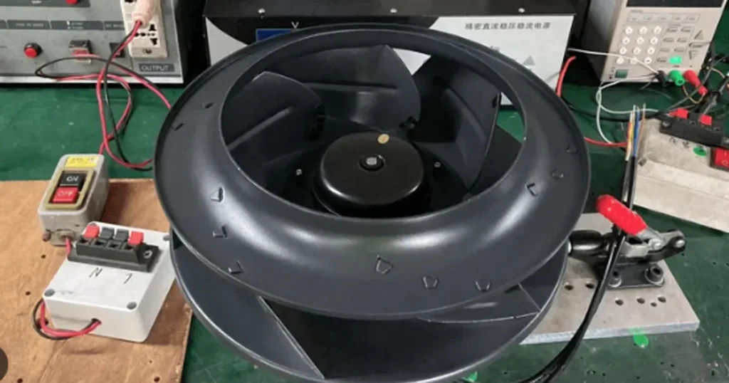
An EC fan can have two wires, a terminal block with a dozen connections, or something in between. That is why a generic color chart is not a safe wiring diagram. The correct connection depends on the exact fan model, supply, control option and feedback interface you ordered.
The useful way to approach EC fan wiring is to separate it into three circuits. The power circuit runs the motor and its integrated electronics. The control circuit tells the fan how fast to run or whether to enable. The feedback circuit reports speed or a fault to your controller. Once those jobs are separated, the terminal list becomes much easier to read.
The examples apply to industrial equipment with compact EC axial fans and larger EC fan assemblies. The model-specific diagram and local electrical rules still take precedence.
Important: Never identify an EC fan lead by color alone. Confirm the terminal name, voltage and electrical function on the exact datasheet before you energize the fan.
Start with the exact EC fan wiring diagram
Begin with the nameplate and part number, not with a photo of a similar fan. Check the rated input voltage, phase, frequency, maximum current, wiring option and revision of the installation instructions. Two fans with the same frame size can use different controllers and completely different pin assignments.
Mark each connection as power, control, feedback or communication. The table below shows common labels, but it is a reading aid rather than a universal pinout.
| Common label | Typical function | What you must verify |
|---|---|---|
| L, N, PE | Single-phase AC power and protective earth | Rated voltage, frequency, grounding class and protection |
| L1, L2, L3, PE | Three-phase AC power and protective earth | Permitted supply range and whether neutral is used |
| 10V or Vref | Reference output for a potentiometer or sensor | Maximum output current and allowed load |
| E1, AI, 0-10V or CTRL | Analog or PWM speed command input | Signal type, range, frequency, polarity and stop behavior |
| GND or COM | Control-signal reference | Whether it is isolated and which circuit it belongs to |
| FG, TACH or SPEED | Speed pulse output | Output circuit, pull-up voltage, pulse count and current limit |
| RD, ALARM, NO, NC, COM | Rotation detection or fault relay | Normal/fault logic and contact or transistor rating |
| A/B, D+/D- or RSA/RSB | RS-485 communication | Polarity convention, baud rate, address and termination |
Wire colors can be useful after you have matched them to the manufacturer’s table. They are not a substitute for that table. Even protective earth should be confirmed from the terminal marking and installation instructions rather than inferred from a photograph.
How EC fan wiring differs from AC and DC fan wiring
An electronically commutated fan uses a brushless permanent-magnet motor and an electronic drive. In many industrial EC fans, the drive accepts AC mains and converts it internally before controlling the motor windings. That is why an EC fan can use ordinary AC power while still offering smooth electronic speed control.
This arrangement is different from a conventional shaded-pole or capacitor-run AC fan, where the supply is closely tied to motor speed, and from a low-voltage DC fan that receives DC power directly. If you need a refresher on the motor and controller architecture, see EC Fan Technology.
The practical consequence is that mains power and the low-voltage command are often separate. Removing the speed signal does not necessarily isolate the motor. Likewise, opening a control contact is not the same as disconnecting line voltage. Treat the power terminals as energized until the correct disconnecting and verification procedure has been completed.
Power wiring: line, neutral and protective earth
A single-phase EC fan commonly uses L, N and PE. A three-phase model may use L1, L2, L3 and PE, with or without a neutral according to its design. Compact double-insulated products can have a different arrangement. Use the exact manual to decide conductor count, protective-earth requirements, fuse or breaker rating, disconnecting means, cable temperature rating and terminal torque.
Do not feed a 110-120 V fan from a 220-240 V circuit because the connector fits. Do not assume a wide-voltage input unless it is printed on the product data. FANACDC’s EC fan range, for example, includes 110-240 VAC designs and optional control functions, but the approved wiring still comes from the selected model sheet.
For workplace equipment in the United States, OSHA 29 CFR 1910.333 requires electrical work practices that prevent shock and calls for de-energizing, lockout or tagout, and verification as applicable. A stop command, interlock or BMS point is not an energy-isolating device.
Safety note: EC electronics can contain stored energy. Isolate every supply, follow the stated discharge time and verify absence of voltage before touching power terminals.
Should you switch mains power or the control signal?
If the fan has a dedicated enable or speed input, normal start-stop control is often performed through that input while the electronics remain powered. This avoids treating the mains contactor as a routine speed controller. It is not a universal rule: the installation manual defines whether permanent power is expected, whether an enable input is required and how often power cycling is allowed.
Also check the fail-safe state. Some fans stop at 0 V; others run at a configured minimum speed, and some can be programmed to run at full speed if the command wire opens. Decide what the equipment should do after a broken control wire before you choose the logic.
Speed-control wiring
The phrase “EC fan speed control” describes several interfaces. A controller that produces 0-10 V is not automatically compatible with a PWM-only input, and a PWM output from a PLC may have the wrong amplitude or reference even when the frequency looks reasonable.
0-10 V analog input
A basic analog connection uses the controller’s signal output to the fan’s analog input and connects the corresponding signal references. If the fan provides a 10 V reference output, a potentiometer can often be wired between 10 V and GND with its wiper feeding the analog input. Confirm the resistance range and the maximum current available from the reference output.
Do not tie together two independent 10 V sources. Do not use protective earth as the signal return unless the schematic explicitly says to do so. A current loop or non-isolated PLC output may need an interface module. One current EC motor instruction manual, for example, separates the E1 analog input, GND and 10 V reference and explicitly warns against applying line voltage to the analog input.
The command-to-speed relationship may include a start threshold, dead band, minimum speed or inverted scaling. Record the actual RPM at several command values during commissioning instead of assuming that 5 V always equals exactly 50% speed.
PWM control input
For PWM control, verify input amplitude, allowed frequency range, duty-cycle definition, polarity, input current and whether the signal needs an open-collector or push-pull driver. The same duty cycle can produce opposite behavior when one input is active-high and another is active-low.
Keep the PWM command separate from motor power. The fan’s integrated electronics perform the commutation; the external PWM line normally supplies information, not motor current. If you are also comparing low-voltage four-wire fans, What Is a PWM Fan? explains the control principle, but you must still use the EC model’s own interface specification.
Potentiometer, sensor and enable inputs
A local potentiometer is useful during setup or for fixed manual adjustment. A temperature or pressure sensor can provide an analog demand signal when its output range and power requirements match the fan. An enable input may require a dry contact, a jumper to an internal reference or an external logic voltage. These are three different circuit types, so do not bridge terminals until the manual shows the required contact state.
RS-485 and Modbus wiring
Digital control adds device address, baud rate, parity, register mapping and network topology to the electrical connection. Use a daisy chain rather than casual star branches unless the system documentation permits them. Confirm A/B naming at both ends because vendors do not always use the same polarity convention. Terminate the bus at its physical ends and follow the manual for biasing, shielding and common-reference connections.
Network control should have a defined loss-of-communication action. Depending on the application, a fan might hold its last command, fall back to a fixed speed or stop. For cooling critical power electronics, an unintended stop is rarely the safest default.
Speed feedback and alarm wiring
FG and RD are often confused because both can change state when the rotor turns. FG is normally a pulse train used to calculate speed. RD is usually a rotation or fault indication. A relay output provides isolated contacts, while a transistor output needs an external supply and input circuit. The labels alone do not tell you the electrical rating.
| Output | Typical use | Integration check |
|---|---|---|
| FG/tach pulse | Calculate RPM and detect speed loss | Open-collector or driven output, pull-up value, pulses per revolution |
| RD/rotation detect | Binary running or stopped indication | Active state, startup delay and stalled-rotor behavior |
| Alarm relay | Fault input to a PLC or BMS | NO/NC state with power off, contact rating and fault definition |
| Analog output | Speed, pressure or operating-state signal | Output range, scaling, load and common reference |
An open-collector FG output does not create a usable high level by itself. It switches an external pull-up circuit. Choose the pull-up voltage and resistor from the fan’s current and voltage limits, then check that the PLC high and low thresholds are satisfied. The pulse frequency must be converted using the stated pulses per revolution; guessing this value can make a healthy fan appear to run at half or twice its real speed.
When several fans share a speed command, their feedback outputs should usually go to separate monitoring inputs. Do not simply tie open-collector outputs or relay contacts together unless the monitoring design has been reviewed for that arrangement. Fan Sensors provides more background on tachometer and alarm functions.
A practical EC fan wiring workflow
- Record the exact fan part number, voltage, phase, current and option code.
- Obtain the current wiring diagram and connector pin table for that revision.
- Separate power, protective earth, control, feedback and communication circuits on your schematic.
- Confirm the controller output type, signal range, isolation and reference.
- Select conductors, protection, disconnecting means and terminals for the actual current, temperature and environment.
- Define the fan’s behavior for zero command, open wire, controller failure and loss of communication.
- Wire with the supply isolated, then perform continuity, polarity and protective-earth checks.
- Commission at a low command first and confirm airflow direction, current and feedback.
- Test the normal operating range and every required fault response.
- Save the final schematic, fan parameters and measured values with the equipment record.
This sequence catches the expensive errors before they become intermittent field faults. It also gives purchasing and service teams a wiring definition they can reuse when the fan is replaced.
Three common connection arrangements
Power-only EC axial fan
A compact fixed-speed EC fan may expose only its supply connections. Wire the rated input and any required protective earth exactly as shown, then verify the airflow direction and running current. Do not expect speed control, FG or alarm functions unless the ordered variant provides them.
Single-phase EC fan with 0-10 V control
The mains circuit connects to L, N and PE. The control circuit connects the controller’s analog output to the fan’s speed input and the correct signal reference. If a start-enable contact is required, include it as a separate condition. During commissioning, record command voltage, RPM, current and system airflow at several points.
PLC control with FG speed feedback
The PLC sends the specified analog or PWM command and receives the FG pulse on a high-speed or digital input. If the FG output is open collector, add the approved pull-up. Program a startup allowance and a minimum-speed threshold so the PLC does not declare a fault while the rotor is still accelerating or intentionally running slowly.
Commissioning tip: A spinning fan is not proof that the interface is correct. Test the full command range, feedback scaling, broken-wire response and alarm state before closing the panel.
Cable routing, grounding and EMC
Route low-voltage control and communication cable away from mains conductors and motor leads. Cross power wiring at right angles when separation cannot be maintained. Use twisted pairs for differential communication and follow the fan manual for shield termination. Connecting a shield at the wrong points can create a ground loop; leaving it floating everywhere can remove its EMC benefit.
Keep control cable runs within the stated limit and avoid sharing a signal common with unrelated high-current loads. Provide strain relief, protect cable edges and maintain the enclosure’s ingress rating with suitable glands. In a washdown, refrigeration or outdoor assembly, the cable entry and connector can be the weakest part of an otherwise protected fan.
EC input electronics can also affect residual-current-device selection and leakage behavior. This is an electrical design question, not a reason to omit protection. Have a qualified designer select the protective device using the fan manual and the rules that apply at the installation.
Commissioning checks before full-speed operation
Before energizing, compare every terminal against the released schematic and inspect for loose strands, reversed connectors and missing protective earth. Check insulation and continuity with test methods that will not damage the electronics. Confirm that the impeller turns freely and that tools, packing and loose wires are outside the rotating area.
Start with the lowest valid command. Watch the direction of rotation and airflow, listen for rubbing, and compare current with the expected operating range. Increase the command in steps while recording voltage or duty cycle, RPM, current and any alarm state. Then test the fan in the assembled equipment, because a filter, guard or restricted outlet moves the operating point.
Finish by simulating the failures your control logic claims to detect: remove the command wire, interrupt communication, block the rotor only if the manufacturer’s approved test permits it, and disconnect the feedback input at a safe point. Confirm how the system recovers after power returns.
EC fan wiring troubleshooting
| Symptom | Likely causes | Useful checks |
|---|---|---|
| Fan does not start | No mains supply, enable input open, command below start threshold, active alarm or wrong model voltage | Measure the correct terminals safely; check enable logic and the commanded value |
| Fan runs only at full speed | Open control wire, missing signal reference, wrong input mode or configured fail-safe | Measure command at the fan input and review parameter settings |
| Speed is unstable | Noisy analog signal, ground offset, unsuitable PWM, poor shielding or unstable control loop | View the signal with suitable test equipment and separate control wiring from power |
| No FG reading | Missing pull-up, incorrect voltage, wrong pulse input or feedback option not fitted | Check the output circuit and observe pulses at a known speed |
| RPM reading is wrong | Incorrect pulses-per-revolution value or counter time base | Compare calculated RPM with a calibrated tachometer |
| Communication drops out | Reversed A/B, duplicate address, star wiring, missing termination or shield/reference problem | Check topology, settings and signal quality from one end of the bus |
| Breaker or RCD trips | Wiring fault, unsuitable protective device, combined leakage, inrush or damaged electronics | Isolate branches and have a qualified person compare measurements with the manual |
Do not bypass a protective device or apply a random voltage to a control terminal as a shortcut. If the wiring checks out but the fan still behaves incorrectly, compare the connector option and programmed interface against the purchase specification.
What to specify when ordering an EC fan
A complete wiring request should state more than voltage and airflow. Send the rated supply, phase, required connector or lead length, control signal, enable behavior, feedback type, alarm logic, communication protocol, environmental rating and applicable approvals. Also state what the fan must do if the command fails.
For OEM work, include the controller’s electrical characteristics and the proposed schematic. LINKWELL can then match the fan option to the interface instead of leaving your panel team to adapt an incompatible signal after samples arrive. See the available EC axial fan sizes and control options or send the application duty point for a model review.
FAQ
What wires does an EC fan need?
A basic EC fan may need only its power conductors and any required protective earth. A controllable model can add analog or PWM command, signal ground, enable, tachometer, alarm or communication wires. The exact part number determines the connection set.
Can I wire an EC fan directly to AC power?
Only when the fan is rated for that AC voltage and the model instructions show a direct mains connection. Some products called EC fans use low-voltage DC input, and controllable AC-input models may also need an enable or speed command.
Are EC fan wire colors standardized?
No universal color scheme covers all manufacturers and options. Protective conductors may follow local conventions, but control, FG, RD and communication colors vary. Use terminal labels and the model-specific pin table.
How do I wire a 0-10 V controller to an EC fan?
Connect the controller output to the fan’s specified analog input and connect the correct signal references. Verify isolation, polarity, voltage range and zero-signal behavior. Do not connect an external 10 V source to the fan’s 10 V reference output.
Can one 0-10 V output control several EC fans?
Sometimes, if the controller can drive the combined input load and the fan manufacturer permits the shared reference arrangement. Calculate the total input current, consider isolation and cable length, and keep feedback outputs separate unless the monitoring design supports combining them.
What is FG on an EC fan?
FG usually means frequency-generator or tachometer output. It produces pulses related to rotor speed. You need the output type and pulses-per-revolution value to design the input circuit and calculate RPM correctly.
What is RD on an EC fan?
RD usually means rotation detection. It provides a running, stopped or fault state rather than a continuous speed value. Confirm whether the signal is active-high or active-low and what happens when fan power is removed.
Why does my EC fan run at full speed when the control wire is disconnected?
The input may be configured for a fail-safe full-speed state, the signal reference may be missing, or the controller mode may be wrong. Measure the command at the fan, review the parameter settings and verify the open-wire behavior in the exact manual.

