
You can estimate the airflow for an electrical enclosure from two values: the heat that must be removed and the temperature rise you can allow above ambient. That calculation gives you a thermal airflow target. It does not give you the final free-air rating to order, because the filter, outlet grille, cabinet openings, and internal obstructions add resistance and move the fan to a different operating point.
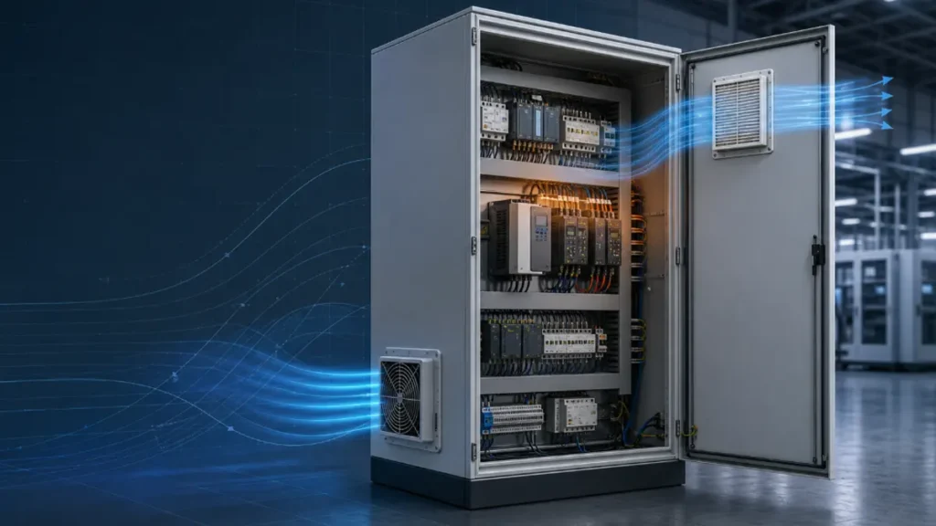
For a reliable selection, calculate the required m3/h or CFM first, then check the fan’s pressure-airflow curve with the intended intake and exhaust filters installed. If you skip that second step, a fan that looks large enough on paper can deliver much less air in the cabinet.
Key Takeaways
- Start with the cabinet heat load and the maximum acceptable temperature rise above ambient.
- Use one unit system consistently; the metric shortcut and the imperial shortcut use different constants.
- A free-air fan rating is not the airflow you will receive through filters, grilles, and a populated enclosure.
- Select from the fan pressure-airflow curve at the expected system resistance, then allow for filter loading.
- Correct for altitude, high inlet temperature, voltage tolerance, and other conditions that reduce cooling margin.
- Validate the result after installation with representative load and temperature measurements.
Quick Filter Fan Airflow Formulas
| Units | First-Pass Formula | Use When |
|---|---|---|
| Metric | Airflow (m3/h) = 3.0 x heat load (W) / temperature rise (deg C) | Your heat load is in watts and temperatures are in Celsius |
| Imperial | Airflow (CFM) = 3.16 x heat load (W) / temperature rise (deg F) | Your heat load is in watts and the temperature difference is in Fahrenheit |
| Mixed | Airflow (CFM) = 1.76 x heat load (W) / temperature rise (deg C) | Your heat load is in watts but you need a CFM result from a Celsius temperature difference |
These constants are based on the heat capacity and approximate density of air near normal room conditions and sea level. They are suitable for a first estimate. Air density changes with altitude and temperature, so high-altitude or unusually hot applications need correction and validation.
Do not mix the 3.16 constant with a Celsius temperature difference. That formula expects a Fahrenheit difference. Mixing the units overstates the required CFM by a factor of about 1.8.
Step 1: Calculate the Internal Heat Load
Use the heat dissipated inside the enclosure, not the sum of every device’s input rating. A power supply that draws 500 W and delivers most of that power to an external load does not necessarily release 500 W as cabinet heat. Use manufacturer loss data, efficiency data, measured losses, or a documented engineering estimate.
Add the losses from drives, power supplies, PLCs, contactors, transformers, braking components, communications equipment, and other internal sources at the worst credible operating condition. Include future loads only when they are part of the design requirement.
If the cabinet is outdoors, solar heat gain may add to the thermal load. If the enclosure surface loses significant heat to cooler ambient air, a detailed thermal model can reduce the load that ventilation must carry. For a conservative first pass, you can assume the airflow removes the full internal heat load, then refine the result with enclosure geometry, material, installation, and ambient conditions.
Step 2: Define the Allowable Temperature Rise
Temperature rise is the difference between the maximum permitted internal air temperature and the maximum design ambient temperature:
Delta T = maximum internal temperature – maximum ambient temperature
Suppose the hottest expected ambient air is 35 deg C and you want the cabinet air to remain at or below 50 deg C. Your allowable rise is 15 deg C.
Use the limit of the most temperature-sensitive component after applying the component manufacturer’s derating rules. Do not use an average room temperature if the cabinet sits near an oven, roof, transformer, or another local heat source.
If ambient air can reach or exceed your maximum acceptable cabinet temperature, increasing fan airflow will not solve the problem. A filter fan uses ambient air and cannot cool below ambient. You may need a heat exchanger, air conditioner, or another closed-loop cooling method.
Step 3: Calculate the Thermal Airflow
Consider a control cabinet with:
- Internal heat dissipation: 600 W
- Maximum ambient temperature: 35 deg C
- Maximum allowable internal temperature: 50 deg C
- Allowable temperature rise: 15 deg C
Using the metric formula:
Required airflow = 3.0 x 600 / 15 = 120 m3/h
Using the mixed-unit CFM formula:
Required airflow = 1.76 x 600 / 15 = 70.4 CFM
The two answers describe approximately the same airflow. They are a thermal minimum under the assumptions of the simplified calculation – not a recommendation to order a fan with a 70.4 CFM free-air label.
Step 4: Account for Filter and Cabinet Resistance
The fan operates where its pressure-airflow curve intersects the resistance curve of the complete system. As resistance increases, an axial fan normally delivers less airflow. Your intake filter, exhaust filter, louvres, finger guards, narrow openings, internal plates, heat sinks, cable ducts, and wiring all contribute.
A dirty filter moves the operating point again. This is why one fixed filter derating percentage cannot be accurate for every design. The loss depends on filter media, area, loading, fan curve, outlet configuration, and cabinet flow path.
Use this order:
- Calculate the thermal airflow target.
- Identify the proposed intake fan filter and exhaust filter.
- Obtain the P-Q curve or airflow data for that configuration.
- Estimate or measure system resistance at the target airflow.
- Confirm that the fan operating point remains above the required airflow.
- Check the result again at the planned filter replacement threshold.
Some LINKWELL fan filter configurations publish different airflow values depending on the outlet-filter arrangement. Use the value for the exact model and layout. Do not transfer a percentage from one fan size or filter family to another.
Step 5: Check the Airflow Path
Good calculations cannot rescue a short or blocked flow path. Install the filtered intake low on a cooler side and place the exhaust high on the opposite side when the cabinet layout permits. Air should pass over the components that create heat rather than travelling directly from inlet to outlet.
Keep cable bundles and internal mounting plates away from both openings. If a large drive or partition blocks the path, use baffles or reposition the openings. You may need more than one intake or outlet in a large cabinet, but each configuration must be checked as a system.
You can review the broader layout considerations on LINKWELL’s electrical enclosure cooling page.
Altitude and High-Temperature Corrections
Air becomes less dense as altitude increases and as temperature rises. The same volumetric airflow then carries less mass, so it removes less heat for the same temperature difference. At high altitude, increase the required volumetric flow using the applicable air-density ratio or perform the calculation with local air density.
The general relationship is:
Volumetric airflow = heat load / (air density x specific heat x temperature rise)
Use consistent SI units when applying the full equation. Ask for an engineering review when the cabinet operates at significant altitude, in a hot environment, or across a wide temperature range.
Common Calculation Mistakes
- Using equipment input power instead of actual heat dissipation
- Mixing a Fahrenheit constant with a Celsius temperature difference
- Comparing the result directly with free-air CFM
- Ignoring the exhaust filter and internal obstructions
- Assuming every filter causes the same percentage loss
- Ignoring solar gain for outdoor enclosures
- Expecting a fan to cool below ambient temperature
- Adding a large safety factor without checking whether the selected fan can overcome the pressure
- Failing to verify temperature after installation
What to Send for a Filter Fan Recommendation
Provide the following data so the calculation can be matched to a real product:
- Internal heat dissipation in watts
- Maximum ambient and maximum allowable internal temperatures
- Altitude and indoor or outdoor location
- Cabinet dimensions, panel layout, and available cutout
- Required AC or DC voltage and frequency
- Dust, moisture, corrosion, and required IP level
- Intake and exhaust filter arrangement
- Target airflow, noise, certification, and maintenance conditions
LINKWELL can compare these values with suitable AC fans, DC fans, and cabinet fan filter configurations. Send your thermal and cabinet data for model selection.
Where the 3.0 Metric Constant Comes From
The common metric shortcut is based on the sensible-heat balance of moving air:
Airflow (m3/h) = 3.0 x heat load (W) / allowable temperature rise (deg C)
The constant is not arbitrary. Starting with heat = mass flow x specific heat x temperature rise, using air density of about 1.2 kg/m3 and specific heat of about 1,005 J/(kg x K), then converting seconds to hours gives approximately 2.99. It is normally rounded to 3.0 for an initial enclosure calculation.
That shortcut assumes conditions near ordinary sea-level air and treats the cabinet as a steady sensible-heat problem. It does not include extra margin for a loaded filter, a restrictive grille, high altitude, unusually hot or low-density air, voltage tolerance, or component growth. It also does not tell you the static pressure at which the fan must deliver the result.
Worked Airflow Examples
| Estimated heat load | Allowed rise above ambient | Calculated airflow | Approximate airflow in CFM |
| 150 W | 10 deg C | 45 m3/h | 26.5 CFM |
| 600 W | 15 deg C | 120 m3/h | 70.6 CFM |
| 1,200 W | 10 deg C | 360 m3/h | 211.9 CFM |
Take the 600 W case. If the factory ambient can reach 35 deg C and your selected internal limit is 50 deg C, the available rise is 15 deg C. The initial result is 3.0 x 600 / 15 = 120 m3/h. You should not now buy the first fan labeled 120 m3/h. You need at least that flow through the installed filter, outlet, and cabinet at the expected resistance.
Be careful when choosing the internal temperature limit. It should come from the most temperature-sensitive component, its derating data, the desired service-life margin, and local hot spots, not only from a general cabinet target. If the design is still open, work through enclosure temperature control before locking the airflow.
From Thermal Airflow to a Fan Operating Point
A thermal formula gives you a required volume flow. A fan curve tells you whether a particular fan can supply that flow against resistance. The intersection of the fan pressure-airflow curve and the cabinet system curve is the operating point. Filters, louvers, outlet grilles, narrow passages, densely packed components, and sharp internal turns all add resistance.
- Calculate the clean-system thermal airflow requirement.
- Build a realistic pressure-drop estimate for the intake filter, outlet, and internal path. Use supplier data when available.
- Add an engineering margin for filter loading, tolerances, altitude, and future heat-load growth. Document the reason for the margin instead of using an unexplained percentage.
- Select the fan at the required airflow and static pressure, not at zero pressure.
- Check sound, input power, voltage, frequency, approvals, bearing life, and the allowed ambient range.
If the required pressure is too high for a typical axial filter fan, changing the layout or increasing the vent area may be better than simply choosing a larger frame. Where the system genuinely needs higher pressure, review whether a centrifugal fan is more appropriate. You can also use our cabinet cooling fan sizing guide as a companion to this calculation.
Commissioning Measurements That Close the Calculation Loop
The calculation is complete only after the cabinet is tested. Run the equipment at a representative or worst credible load with the doors closed, the production filter fitted, and the final control settings active. Record ambient air temperature, intake temperature, outlet temperature, and cabinet temperatures near the critical components. Allow the readings to stabilize.
Confirm the direction of both the fan and the full cabinet flow path. Smoke visualization or safe airflow indicators can reveal recirculation and dead zones, but use a method permitted by your site. The layout guidance in cabinet fan airflow direction can help you interpret the result.
Keep a clean-filter baseline. Later maintenance teams can compare temperature, air velocity, or pressure with that baseline and replace the media based on condition. If your measured rise is higher than calculated, check whether the heat estimate was incomplete, the actual ambient is hotter, the flow is restricted, the outlet is undersized, the fan is rotating incorrectly, or heated outlet air is being drawn back into the intake.
When the Simple Formula Is Not Enough
Use a more detailed thermal review when heat is strongly localized, the enclosure is outdoors in solar load, internal circulation is poor, the installation is at significant altitude, or reliability depends on small temperature margins. The shortcut is also unsuitable if ambient air is at or above the required internal temperature. Ventilation cannot cool below ambient.
In wet, corrosive, highly contaminated, or temperature-controlled applications, bringing ambient air through a filter may itself be unacceptable. A sealed air-to-air heat exchanger or enclosure air conditioner may be the better architecture. Compare the tradeoffs in enclosure fan vs air conditioner before increasing airflow in a system that should remain closed.
Frequently Asked Questions
How do I calculate CFM from watts and Celsius?
For a first estimate near normal room conditions and sea level, use CFM = 1.76 x heat load in watts / allowable temperature rise in deg C. Then verify the fan operating point against filter and cabinet resistance.
How much extra airflow should I add for a filter?
There is no universal percentage. Use the selected fan’s P-Q curve and the pressure drop or installed airflow data for the actual intake and exhaust arrangement. Apply design margin for uncertainty, loading, altitude, and future heat only after those effects are understood.
Should I calculate airflow from cabinet volume?
Volume and air changes can be useful for some ventilation tasks, but heat-producing electrical enclosures should primarily be sized from heat dissipation and allowable temperature rise. A small cabinet with a large drive may require more airflow than a much larger cabinet with little heat.
Why is measured airflow lower than the datasheet value?
The datasheet value may be free-air airflow. Filters, grilles, cutouts, outlet restrictions, internal components, altitude, supply conditions, and measurement method can all reduce the installed result.
Can two exhaust filters increase airflow?
They can reduce outlet resistance when they provide more effective open area, but the improvement depends on the fan curve and cabinet layout. Use configuration-specific data rather than assuming the airflow will double.

