
The fan has power, but the controller still reports a cooling fault. In another machine, the fan is visibly blocked and no alarm appears. Both problems can come from treating the RD wire as a universal signal with a universal logic level.
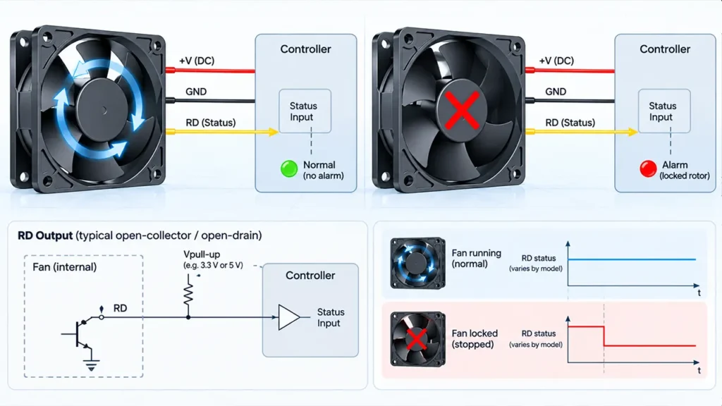
An RD signal—often described as a rotation-detection, locked-rotor or alarm output—tells the host system whether the fan is rotating or stopped. It is normally a status signal, not a continuous measurement of speed. Its output circuit, active state, startup delay and wiring must be confirmed for the exact fan model.
What Is a Fan RD Signal?
A fan RD signal is an electrical output used by a controller to detect a stopped or locked fan. When the rotor state changes, the output changes between two electrical states. The equipment can then log a fault, switch to a backup fan, reduce power, start a controlled shutdown or notify maintenance.
The letters used on drawings are not completely uniform. RD may mean rotation detection, rotor detection or a related alarm function. Other documentation may use alarm, lock, locked-rotor or failure output. The function description and waveform are more important than the abbreviation.
Note: Do not connect an RD wire to a controller until the output circuit, maximum voltage, logic states and required pull-up have been checked for that model.
RD Signal, FG Signal and Locked-Rotor Protection
These functions are related but solve different problems.
| Function | What it does | What the controller receives |
|---|---|---|
| RD or alarm signal | Indicates rotating versus stopped or locked status | A state change or model-specific alarm level |
| FG or tachometer signal | Provides pulses related to rotational speed | A pulse train that can be converted to RPM |
| Locked-rotor protection | Limits stress inside the fan during blockage | Possibly no external signal at all |
| Automatic restart | Periodically attempts to restart after a blockage is removed | RD may change as the fan stops and retries |
A fan may protect itself during a rotor lock but provide no alarm wire. Another model may provide both protection and RD output. A third may provide FG pulses but no dedicated alarm. Check the option code rather than assuming every fan in a series has the same functions.
For more detail on the protection function itself, see Fan Locked Rotor Protection. The pulse-output side is covered in Fan Tachometer Signal.
How a Locked-Rotor Alarm Output Works
The fan’s internal electronics monitor motor commutation or rotor movement. When rotation is present, the alarm output stays in one state. When movement stops for longer than the internal detection period, the output changes state.
The exact timing matters. During power-up, the rotor needs time to accelerate. A controller that checks the alarm immediately can report a false failure before the fan has had a chance to start. During automatic restart, the signal may also alternate as the fan attempts to run.
Because internal detection methods differ, do not promise a universal response time or logic state. Use the model datasheet or an approved test waveform.
Why RD Logic Is Not Universal
One fan may pull the signal low during normal rotation and release it during a fault. Another may use the opposite convention. Some models use a latched alarm; others follow the current rotor state. The signal at startup, power-off and commanded stop may also differ.
This is why a wiring diagram should state the meaning of each state rather than label the wire only as “RD.” A complete interface description includes:
- Normal-rotation output state
- Stopped or locked output state
- Power-off state
- Startup and detection delay
- Automatic-restart behavior
- Output circuit and electrical limits
Open-Collector and Open-Drain RD Outputs
Many alarm outputs are implemented as open-collector or open-drain circuits. Instead of actively driving both high and low levels, the fan’s transistor pulls the signal toward ground in one state and becomes high impedance in the other. The host circuit supplies the high level through a pull-up resistor.
This arrangement can make it easier to interface the alarm with different controller logic voltages, but only within the fan output’s stated limits. The pull-up voltage, resistor value and input threshold must suit both the fan transistor and the controller.
If the pull-up is missing, the signal can float and produce random readings. If the pull-up resistance is too low, current may exceed the output rating. If it is too high, leakage, cable capacitance or electrical noise may prevent a clean transition.
Do Not Assume the Fan Supplies the High Level
A multimeter may show an undefined or unstable voltage on an unconnected open-collector output. That does not necessarily mean the alarm is defective. Test it with the specified pull-up and load condition.
Use a Common Reference
The controller and fan signal normally need a compatible reference ground. Poor grounding, long cables and shared motor current paths can add noise to the signal. Route the RD wire away from switching power conductors where practical and evaluate filtering at the controller.
How to Wire an RD Signal to a Controller
Begin with the fan wiring drawing. Identify power, ground and RD conductors by pin number, not only by color. Confirm whether the output can connect directly to the controller input or requires a pull-up, level translation, isolation or protection.
For an open-collector or open-drain output, a typical interface includes the RD output connected to a digital input and a pull-up resistor connected to the controller’s approved logic rail. The exact values and voltage limits must come from the fan and controller specifications.
Long cables in industrial equipment may need additional noise control. A simple software delay can reject startup transitions, but it does not correct an electrically incompatible interface. Address signal integrity first, then set the diagnostic timing.
Startup Delay, Debounce and Fault Timing
A useful fan alarm should detect a real loss of cooling without creating nuisance faults. The controller therefore needs timing rules for startup, speed changes and brief disturbances.
At power-up, allow the fan to reach a detectable rotation state before evaluating RD. If the fan is speed-controlled, consider whether a very low command can produce a valid running state. If automatic restart is enabled, decide whether the system should alarm immediately, after several failed attempts, or after a temperature condition is also met.
Debounce should be long enough to reject short electrical transitions but not so long that a real cooling failure remains hidden. The correct delay depends on fan behavior and equipment thermal margin; it should be verified during testing.
RD Signal Behavior During Commanded Stop
Some systems intentionally stop fans at low temperature. From the fan’s point of view, the rotor is not rotating, so the RD output may look the same as a mechanical blockage. The host controller must distinguish “commanded off” from “expected to run but stopped.”
One method is to evaluate RD only when the fan enable or PWM command requests rotation. Another is to use a state machine that tracks startup, running, commanded stop and fault conditions. Do not suppress all alarms at low speed without testing because a fan can also fail while a low-speed command is active.
How to Test a Fan RD Signal
- Confirm the model, option code, pinout and rated supply.
- Connect the output using the required pull-up and controller reference.
- Record the RD state with the fan unpowered.
- Apply power and observe the startup transition and delay.
- Confirm the steady running state at normal speed.
- Command minimum speed and verify that the state remains valid.
- Use a safe test fixture to prevent rotation without placing hands or tools in the impeller.
- Record the time from loss of rotation to alarm state.
- Remove the obstruction and observe automatic-restart and alarm recovery behavior.
- Repeat with the actual cable, controller input and expected electrical noise present.
An oscilloscope or logic analyzer is more useful than a multimeter when the signal changes briefly during startup or restart. The final test should also confirm that the equipment reacts correctly—for example, by logging a fault or transferring to redundant cooling.
Common RD Signal Problems
| Symptom | Possible cause | Check |
|---|---|---|
| Alarm is always active | Reversed logic, wrong pin, missing supply or actual stalled fan | Pinout, truth table and rotor state |
| Alarm never appears | No pull-up, incompatible voltage, wrong option or controller threshold | Output circuit and option code |
| False alarm at power-up | Controller checks before the fan accelerates | Startup delay and firmware timing |
| Random alarm during switching | Ground noise, long cable or weak pull-up | Routing, reference ground and signal waveform |
| Alarm during intentional stop | Controller does not track commanded fan state | Enable logic and diagnostic state machine |
What to Specify When Buying a Fan with RD Output
State the supply voltage, fan size, required airflow and pressure, cable length, connector, output circuit, pull-up voltage, normal and fault logic, response timing, automatic-restart requirement and environmental conditions. If the controller already exists, share its digital-input specification.
LINKWELL offers different control and feedback options depending on the fan model. Confirm RD availability and electrical behavior on the selected part number before approving the wiring or firmware.
Frequently Asked Questions
What does RD mean on a cooling fan?
It generally refers to a rotation-detection or locked-rotor alarm output that indicates whether the fan is rotating or stopped. The exact naming and logic vary by model.
Is RD the same as FG?
No. RD normally provides a status state, while FG or tachometer output provides pulses related to speed.
Does an RD signal protect the fan?
Not by itself. RD reports a state to the host. Locked-rotor protection is an internal function that limits stress during blockage.
Does an RD wire need a pull-up resistor?
Many open-collector or open-drain outputs do, but the correct interface must be confirmed from the exact fan specification.
Can wire color identify the RD signal?
No. Wire colors can vary between fan models and custom assemblies. Use the approved pinout.
Why does RD show a fault when the fan is intentionally stopped?
The fan detects no rotation. The controller must evaluate RD together with the command that requests the fan to run.

