
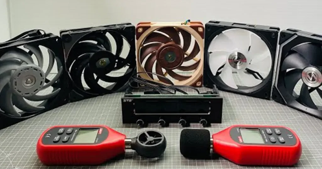
Hold an anemometer in front of a fan and you will get a number. That number is usually air velocity at one small point, not the fan’s total airflow. The center of the outlet may be fast, the corners slow, and part of the flow may be angled or even recirculating.
Reliable fan airflow measurement starts with a defined boundary: a duct cross-section, a grille face, a flow hood or a standardized test chamber. You measure enough of that boundary to find an average, then convert the result into CFM, m3/h or another volumetric flow unit.
The right method depends on the decision you need to make. A quick field check can confirm whether airflow fell after a filter loaded. It cannot replace a laboratory performance curve for a production fan. Keeping that distinction clear prevents a rough reading from becoming a false product rating.
Key point: A single velocity reading at the center of a fan does not equal total airflow. You need an average across a known area, or a test device that measures volume flow directly.
Decide what you are trying to measure
“Fan airflow” can mean four different things. You may want the free-air output of a bare fan, the airflow through installed equipment, the volume leaving a register, or the flow through a heat exchanger or filter. Each question needs a different test boundary.
| Measurement objective | Useful setup | What the result means |
|---|---|---|
| Rate a fan for a datasheet | Standardized chamber or airway with pressure and flow measurement | A repeatable pressure-flow performance point or curve |
| Verify airflow in an enclosure or machine | Duct traverse, calibrated flow station, or controlled inlet/outlet measurement | Installed airflow with the real filter, guard and system resistance |
| Balance a supply or exhaust outlet | Flow hood or grille traverse | Volume flow through that outlet under the test condition |
| Compare before and after maintenance | Repeatable field method at the same location and operating state | Change in airflow, even if absolute accuracy is limited |
| Check cooling effectiveness | Airflow measurement plus component and inlet temperature tests | Whether the air reaches the heat sources and removes enough heat |
Write the objective before choosing the instrument. If the requirement says “500 CFM through the loaded filter at 90 Pa,” a free-air reading is not relevant. If the purpose is a production acceptance test, specify the method, tolerance, air density and equipment state so the supplier and customer measure the same thing.
Air velocity and volumetric airflow are not the same
Air velocity tells you how fast air moves at a location. Volumetric airflow tells you how much air crosses an area in a given time. The basic relationship is:
Q = Vavg × A
Q is volumetric airflow, Vavg is the average velocity across the measurement plane, and A is the internal flow area. If velocity is in feet per minute and area is in square feet, Q is in cubic feet per minute. If velocity is in meters per second and area is in square meters, Q is in cubic meters per second.
The word average matters. Duct velocity is lower near the walls and usually higher toward the center. Bends, dampers, fans and branch fittings can make the profile strongly uneven. One center reading can therefore overstate the average by a large amount.
Area formulas and useful conversions
For a rectangular duct, multiply the internal width by the internal height. For a round duct, use A = π × D² / 4, with D as the internal diameter. Subtract any solid obstruction if it materially reduces the open area.
| Conversion | Value |
|---|---|
| 1 m3/s to m3/h | Multiply by 3,600 |
| 1 m3/s to CFM | Approximately 2,119 CFM |
| 1 CFM to m3/h | Approximately 1.699 m3/h |
| 1 inch to feet | Divide by 12 before calculating square feet |
Keep one unit system through the calculation. A common mistake is multiplying velocity in feet per minute by an opening area still written in square inches.
Choose the right fan airflow measurement method
No single instrument is best for every installation. The method should match the velocity range, available straight duct, flow direction, required accuracy and physical size of the fan.
Duct traverse with a Pitot-static tube
A Pitot-static tube measures velocity pressure. With air density, that pressure is converted to velocity. You take readings at prescribed points across the duct and average them before multiplying by duct area. This method works well at moderate and higher duct velocities when the pressure signal is large enough for the manometer.
Probe alignment matters. Swirling or reverse flow can produce misleading readings, especially near a bend, tee or fan outlet. A negative velocity-pressure reading is a strong sign that the traverse plane is unsuitable or the probe is misaligned.
Hot-wire anemometer traverse
A hot-wire probe is sensitive at low velocities and fits into small ducts. It can be a practical choice for electronics cooling, clean-air systems and low-flow HVAC measurements. It still measures a point, so you need a traverse rather than one reading. Temperature, probe orientation, contamination and reverse flow can affect the result.
Vane anemometer or grille traverse
A rotating vane averages velocity over a larger sensor area than a hot-wire probe. It is convenient at large grilles, filters and open faces. Divide the face into equal areas, take readings in each zone and average them. Use the effective open area when a grille or louver blocks part of the nominal face.
Flow hood or capture hood
A flow hood captures the air from a register or grille and reports volume flow directly. It is faster for balancing many outlets, but the hood adds resistance and can change the flow it is measuring. Select the correct hood size, center it, seal the edges and use the manufacturer’s backpressure compensation when needed.
Nozzle chamber or standardized fan test rig
A chamber uses calibrated nozzles or another flow-measuring device together with pressure, temperature and speed measurements. It can create several system resistance points and produce a complete fan curve. This is the right level of testing for product ratings, supplier qualification and disputed acceptance results.
Fan curve and pressure measurement
If you know the fan’s installed pressure rise and have a valid curve for the same speed, voltage and air density, you can estimate airflow from the curve. This is useful for diagnosis, but it is an inference rather than a direct flow measurement. A disturbed inlet or outlet can make the installed fan perform differently from its laboratory curve.
| Method | Best use | Main limitation |
|---|---|---|
| Pitot traverse | Straight duct with measurable velocity pressure | Weak signal at low velocity; sensitive to alignment |
| Hot-wire traverse | Low velocity or small ducts | Sensitive to direction, contamination and turbulence |
| Vane traverse | Grilles, filters and large openings | Area and edge effects can dominate the error |
| Flow hood | Supply and exhaust outlets | Hood backpressure can alter the flow |
| Standardized chamber | Fan curves and product verification | More equipment, setup time and expertise |
| Curve-based estimate | Installed troubleshooting | Depends on curve validity and inlet/outlet conditions |
How to perform a duct traverse
A duct traverse is the most useful general field method when you can create a suitable measurement plane. The process is simple in principle, but shortcuts around location and sampling are where most errors enter.
- Choose a straight, constant-area section away from the fan, elbows, dampers, transitions and branches.
- Measure the internal duct dimensions. Do not use the outside sheet-metal dimensions.
- Select a calibrated probe with a velocity range appropriate for the expected flow.
- Lay out traverse points using a recognized method for the duct shape.
- Set the fan, filter, dampers and equipment to the operating condition you want to evaluate.
- Insert and align the probe at each point, allow the reading to stabilize and record it.
- Review the readings for negative values, strong swings or an implausibly uneven profile.
- Average the point velocities and multiply by the internal area.
- Repeat the traverse to check repeatability.
- Record the setup, instrument, calibration date, air condition and calculated result.
The ASHRAE Handbook chapter on measurement and instruments explains why a traverse is needed and describes log-Tchebycheff points for rectangular ducts and log-linear points for round ducts. It recommends locating the plane, when possible, at least 7.5 hydraulic diameters downstream and 3 diameters upstream from a disturbance.
Those distances are not always available inside compact machinery. In that case, do not pretend the profile is ideal. Add a temporary straight measurement duct, use a flow straightener where appropriate, increase the number of points, or choose another method. Document the compromise and use repeat tests to understand its effect.
Measurement note: If moving the probe a small distance changes the reading dramatically, the flow profile is telling you that the test plane is poor. More decimal places will not fix a bad location.
How to measure a small axial fan
A bare compact axial fan is one of the hardest cases for a handheld anemometer. The outlet contains rotating, non-uniform flow, and the meter itself blocks part of the small opening. Holding the sensor against the guard changes the resistance and samples only part of the discharge.
For a useful engineering check, mount the fan to a sealed adapter that feeds a straight measurement duct or a small plenum. Make the cross-section large enough for the probe and long enough for the flow to become more uniform. Prevent leakage around the fan frame and adapter. Measure at a traverse plane, then calculate volume flow from average velocity and area.
That setup measures the fan with the adapter and duct attached, not an untouched free-air condition. For a catalog rating or supplier comparison, use a standardized chamber. ANSI/AMCA 210-25 and ANSI/ASHRAE 51-25 define laboratory methods for aerodynamic performance, while ISO 5801 covers fan performance testing using standardized airways.
When your real goal is equipment cooling, test the assembled equipment too. A fan that measures well on a bench can lose airflow behind a dense filter, close guard, heat sink or crowded cabinet. Use the fan curve and system operating point to connect the bench result with the installed duty.
Measuring airflow at a grille, filter or heat exchanger
At a broad face, mark a grid of equal-area zones and measure near the center of each zone. Average the velocities, then multiply by the effective flow area. If the face is highly uneven, use more points. A few readings only across the center will usually miss low-velocity edges and bypass paths.
Nominal face area and free area are not always the same. Louvers, grille bars and filter frames reduce the open area. A manufacturer may publish an effective area or a calibration factor; use it when available. If you simply multiply face velocity by the full outside dimensions, the airflow can be overstated.
Make sure the air crosses the measurement boundary once. Leakage around the filter frame or recirculation from the discharge back to the inlet can produce respectable local velocity without useful flow through the equipment. Smoke visualization or temporary sealing can reveal these paths.
Worked airflow calculations
Rectangular metric duct
A duct measures 0.30 m by 0.20 m internally. Its area is 0.060 m². A traverse gives an average velocity of 4.2 m/s.
Q = 4.2 × 0.060 = 0.252 m3/s
Multiply by 3,600 to obtain 907 m3/h. Multiply 0.252 m3/s by approximately 2,119 to obtain about 534 CFM. Report the result with sensible precision; 907.2 m3/h would imply more certainty than the field test probably has.
Round imperial duct
An 8-inch internal diameter is 0.667 ft. The cross-sectional area is π × (0.667 × 0.667) / 4, or approximately 0.349 ft². If the average traverse velocity is 900 ft/min:
Q = 900 × 0.349 = 314 CFM
If one center reading had been 1,150 ft/min and you used it as the average, the result would have been 401 CFM, about 28% higher. That is exactly why the traverse matters.
Common airflow measurement errors
| Error | Why it changes the result | Better practice |
|---|---|---|
| One reading at the outlet center | The center is rarely the true average | Use multiple equal-area or prescribed traverse points |
| Measuring directly at the fan guard | Swirl, blade wakes and probe blockage distort velocity | Add a controlled measurement duct or chamber |
| Using outside duct dimensions | The calculated area is too large | Measure the clear internal cross-section |
| Testing near an elbow or branch | The velocity profile can be skewed or reversing | Move the plane, straighten the flow or change method |
| Ignoring grille free area | Velocity is multiplied by an area that air cannot use | Use effective area or a calibrated hood |
| Using an uncalibrated or wrong-range meter | Low or high velocities can fall outside useful accuracy | Match the instrument range and verify calibration |
| Changing the equipment between tests | Filter, doors, speed and dampers move the operating point | Record and reproduce the complete operating state |
| Mixing units | Square-inch, square-foot and metric errors multiply quickly | Convert dimensions before calculating area |
How accurate does your airflow result need to be?
Accuracy should fit the decision. A maintenance trend may only need to show that airflow dropped meaningfully from last month. A thermal design validation needs enough confidence to prove the hottest component stays within limit. A product rating or contractual acceptance test needs a defined standard and uncertainty calculation.
Instrument accuracy is only one part of uncertainty. Add errors from traverse location, number of points, duct dimensions, leakage, unstable fan speed, air density, temperature, probe alignment and data reduction. Repeatability helps you see whether the setup is under control, but a repeatable bias can still be wrong.
Use consistent test conditions. Record supply voltage, fan speed, filter condition, damper position, enclosure doors, ambient temperature and barometric pressure when density matters. For a variable-speed fan, log the actual RPM or feedback signal instead of relying only on a percentage command.
Use measured airflow with the fan curve
A measured flow point becomes much more useful when you also know system pressure. Plot the point against the manufacturer’s P-Q curve for the exact fan and speed. If the measured combination is plausible but lower than the design target, the fan may simply be operating against more resistance than expected.
If the point does not fit the curve, check measurement error, fan speed, air density, leakage and inlet or outlet distortion. A dirty filter shifts the system curve toward lower airflow. A larger vent or smoother path lowers resistance. Fan Speed vs Airflow explains how speed changes the fan curve, while Fan Filter Airflow Calculation focuses on filter pressure loss.
Do not choose a replacement fan from a free-air CFM number when your test point includes pressure. Send the measured airflow, static or total pressure, fan speed and equipment layout to the supplier. That gives the supplier a duty point they can actually select against.
Selection note: A credible installed measurement is more valuable than a larger catalog CFM number. It tells you what the complete airflow path is doing, not just what the fan can do in free air.
What to record in an airflow test report
A short test record should let another technician reproduce the measurement. Include:
- The purpose of the test and the required airflow.
- Fan model, voltage, command, RPM and direction of airflow.
- Filter, guard, grille, damper and enclosure configuration.
- Measurement location with duct dimensions or effective area.
- Instrument model, range, serial number and calibration status.
- Traverse method, point locations and individual readings.
- Average velocity, formula, unit conversions and final airflow.
- Ambient temperature, pressure or density when relevant.
- Repeat readings, observed instability and estimated uncertainty.
For an OEM cooling project, also record component temperatures at the same operating point. FANACDC can review the airflow duty, fan curve and enclosure conditions when you are selecting an industrial axial fan or a higher-pressure centrifugal fan.
FAQ
What tool measures fan airflow?
A hot-wire or vane anemometer measures air velocity, which you can convert to airflow using average velocity and area. A Pitot-static tube measures velocity pressure in a duct. A flow hood or calibrated chamber can measure volumetric flow more directly.
How do I calculate CFM from air velocity?
Multiply average velocity in feet per minute by the internal area in square feet. CFM = average FPM × area in ft². Use several readings across the area rather than one center value.
Can I measure CFM by holding an anemometer in front of a fan?
You can obtain a rough comparison, but the reading is strongly affected by probe position, swirl and blockage. For total airflow, use a grid across a known face or place the fan in a controlled duct or chamber.
Where should I measure airflow in a duct?
Use a straight, constant-area section as far as practical from fans, elbows, dampers, transitions and branches. ASHRAE guidance recommends, when possible, at least 7.5 hydraulic diameters downstream and 3 diameters upstream from a disturbance.
Is CFM the same as fan speed?
No. RPM is rotational speed; CFM is volume flow. Airflow generally changes with speed for the same fan and system, but the installed CFM also depends on pressure resistance, air density and inlet/outlet conditions.
Why is measured airflow lower than the datasheet?
The datasheet maximum may be a free-air value at nearly zero pressure. Filters, grilles, heat exchangers, ducts and crowded inlets add resistance. Voltage, speed, air density, system effect or a poor measurement location can also reduce the result.
Should I measure intake or exhaust airflow?
In a sealed steady-flow system, intake and exhaust volume should be close after accounting for leakage and density change. Measure at the boundary with the most uniform, accessible flow and lowest test uncertainty.
How many anemometer readings do I need?
Use the traverse-point pattern required by your chosen method and duct shape. More points are needed when the profile is uneven or the plane is close to a disturbance. Repeat the traverse and compare results before accepting the average.
Can a fan curve replace airflow measurement?
A fan curve can estimate airflow if you know the pressure rise, RPM, density and inlet/outlet condition. It cannot reveal leakage or all installation effects. Use direct measurement when acceptance, thermal risk or troubleshooting accuracy matters.

