
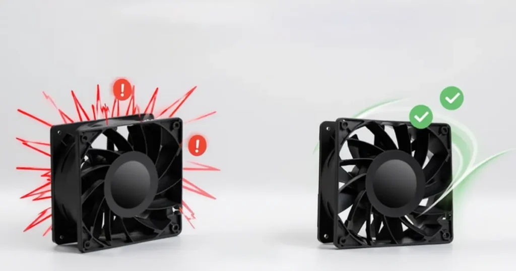
An axial fan that sounds quiet on the bench can become the loudest part of a machine after you add a grille, filter or close cabinet panel. The fan did not necessarily change. Its operating point, inlet flow and vibration path did.
That is why effective axial fan noise reduction starts with diagnosis. A broad rushing sound points toward airflow and turbulence. A narrow whine can come from blade-pass interaction, the motor or PWM control. A rattle or low-frequency hum is more likely to involve balance, bearings, mounting or a resonant panel.
The target is not simply a lower dBA number. The equipment must still deliver the required airflow and keep critical components within temperature limits. A silencer, dense foam or finer filter can make a system quieter while adding enough resistance to create a cooling problem.
Key takeaway: Treat sound, airflow and temperature as one test. A quieter fan solution that misses the cooling duty is not a successful noise reduction.
Identify the noise before you change the fan
Listen for the character of the sound and note when it appears. Does it start at one speed, after the filter loads, only when the cover is installed, or only when two fans run together? A simple speed sweep and a few temporary mechanical changes can separate causes quickly.
| Sound or symptom | Likely source | First check |
|---|---|---|
| Broad rushing or hissing | High air velocity, turbulence, restrictive grille or sharp edge | Temporarily remove nearby restrictions and compare airflow and sound |
| Clear tone that rises with RPM | Blade-pass interaction, inlet distortion, motor commutation or PWM | Run a controlled speed sweep and note the tonal frequency |
| Low hum or panel buzz | Structure-borne vibration, electrical frequency or panel resonance | Measure vibration and brace or damp the suspected panel temporarily |
| Rattle at one speed band | Loose hardware, cable, guard or resonant assembly | Inspect clearances and sweep slowly through the problem speed |
| Scrape, click or repeating tick | Rotor contact, damaged blade, bearing defect or foreign object | Stop and inspect before continued operation |
| Surging or pulsing airflow | Unstable operating region, recirculation or control hunting | Check pressure, fan curve and control-loop behavior |
| Beating with several fans | Slightly different RPM or fan-to-fan interaction | Run each fan alone, then compare synchronized or separated speeds |
Do not keep running a fan that scrapes, shows a sharp rise in vibration or has visible blade damage. Acoustic diagnosis should never take priority over mechanical safety.
Measure a baseline you can repeat
A smartphone reading can help locate a change, but it is not enough for a supplier acceptance limit. Use a suitable sound level meter, define the microphone position and record the operating condition. Keep the distance, angle, room, background noise and equipment configuration unchanged for every before-and-after test.
Sound pressure level depends on the room, distance and reflections. Sound power level describes the acoustic energy emitted by the source under a defined method and is better for comparing products. A datasheet dBA value cannot be compared fairly with a field reading unless the measurement conditions are compatible. What Does dBA Mean? explains these distinctions in more detail.
For laboratory fan sound ratings, ANSI/AMCA Standard 300-24 establishes reverberation-room methods, while ISO 13347-2:2025 covers fan sound power in a reverberant room. These standards address controlled airborne sound measurements; a field test inside a machine also includes the effects of panels, mounting and the surrounding space.
Record at least fan model, RPM or command, voltage, airflow or pressure, filter state, guard and panel configuration, microphone location, background level and ambient condition. If a tone is the complaint, save one-third-octave or narrowband spectrum data rather than only an overall dBA value.
Sound pressure, sound power and workplace exposure
A lower product sound value does not automatically prove that worker exposure is acceptable. Exposure depends on level, duration, distance and all nearby sources. In the United States, OSHA’s occupational noise guidance explains monitoring and hearing-conservation requirements. Treat that assessment as a workplace safety task, separate from choosing a quieter cooling fan.
Check the operating point before adding acoustic material
An axial fan is usually happiest in a stable region of its pressure-flow curve. If the system resistance is too high, the operating point can move toward low flow and unstable blade loading. The result may be more turbulence, a stronger tone and less useful cooling even though the fan is running at full speed.
Filters, close guards, small vent areas, dense heat exchangers and crowded outlets all add resistance. Inlet swirl or a sharp obstruction can also change the fan’s behavior from its laboratory curve. AMCA’s explanation of fan system effect links non-uniform inlet and outlet flow with lost performance, added noise and vibration.
Plot the required duty against the actual fan curve. If the duty lies near an unstable region or beyond the curve, acoustic foam will not solve the cause. Lower system resistance, select a fan with the right pressure capability, or increase fan size so the duty can be met at a lower speed. Use How to Read a Fan Curve when checking the operating point.
Selection note: Maximum free-air CFM is not a noise-control specification. Select the fan at the airflow and pressure your equipment actually needs.
Reduce aerodynamic noise at the source
For most cooling installations, the largest acoustic gains come from making the air path easier and more uniform. That reduces the speed or pressure the fan needs and removes local turbulence that creates broadband noise and tones.
Use a larger fan at a lower speed
If space allows, a larger fan can deliver the same airflow at a lower rotational speed and lower outlet velocity. This often reduces both aerodynamic noise and the risk of a sharp blade-pass tone. Confirm the result at the required pressure; a larger low-pressure fan is not automatically better behind a restrictive heat exchanger.
Variable-speed DC or EC fans make it easier to match airflow to heat load. Set the lowest speed that maintains temperature margin during normal operation, then allow higher speed for hot ambient or peak load. Avoid oversizing so far that the fan spends most of its life in an inefficient or unstable control range.
Give the inlet and outlet room to breathe
A wall, cable bundle, sharp bend or heat exchanger placed very close to the inlet can feed one side of the rotor more heavily than the other. On the outlet, a sudden blockage can create recirculation and high local velocity. Move obstructions away where possible, use a smooth bellmouth or transition, and avoid abrupt area changes.
Uniform flow matters more than a fixed universal clearance number. The required distance depends on fan diameter, guard, wall ring and surrounding geometry. Prototype the real layout. A small change in fan-to-panel spacing can alter both sound and airflow.
Choose guards, grilles and filters by pressure drop
A finger guard is a safety component, but its wire spacing and distance from the blade can influence noise. Stamped grilles and decorative louvers often have less free area than they appear to have. Compare pressure drop at the required airflow, not only the outside dimensions.
Filters add more resistance as they load. Design for the dirty-filter duty and provide enough face area to keep velocity reasonable. If removing a filter makes the fan much quieter, the answer may be a larger filter area or different media rather than operating without filtration. Axial Fan Accessories explains the performance trade-offs of guards, filters, louvers and mounting parts.
Avoid fan-to-obstruction tonal interaction
A stationary strut, grille bar or heat-exchanger edge close to the rotating blades can create a repeating pressure disturbance. That interaction may produce a noticeable tone even when the overall dBA value is modest. Change the axial spacing, rotate the obstruction pattern, or use a tested inlet treatment to break the interaction.
Do not copy a serrated edge, special grille or flow straightener from another fan and assume the same improvement. These features interact with blade geometry and installation. Use supplier test data or an A/B test on the complete assembly.
Plan multiple-fan arrays carefully
Side-by-side fans can ingest each other’s disturbed flow, especially when the inlet plenum is shallow. Fans running at slightly different speeds can produce beating. A stopped fan may also become a leakage or backflow path that forces the remaining units to run faster.
Use matched models and control commands, provide a plenum that distributes inlet flow, and test all intended combinations. If capacity is staged, sweep through each transition and listen for tones rather than validating only all-off and all-on states. The airflow effects of multiple fans are explained in Fans in Parallel vs Series.
Reduce mechanical and structure-borne noise
Mechanical noise begins at the rotating assembly but often becomes loud only after it reaches a large panel. A thin enclosure wall can act like a loudspeaker. Tightening one screw may remove a rattle; over-tightening a distorted fan frame can create a different problem.
Inspect the impeller and bearings
Disconnect power and inspect for dust buildup, damaged blades, rubbing, shaft play and foreign objects. Uneven contamination can create imbalance. Clean with a method approved for the fan materials and electronics, and do not bend a blade to make it look straight. Replace an impeller or fan with cracks, permanent deformation or rough bearings.
A bearing defect often produces a growl, rumble or repeating high-frequency pattern that changes with speed. Lubrication is not a universal repair because many compact fan bearings are sealed. Follow the service instructions rather than adding oil near the motor and electronics.
Check mounting flatness and fastener load
Mount the frame on a flat surface and tighten fasteners evenly. A warped panel or uneven screw torque can twist the frame, reduce blade clearance and transmit more vibration. Use the specified mounting points; do not clamp the fan through areas that were not designed to carry load.
Isolate vibration without making the mount unstable
Elastomer grommets, pads or isolators can interrupt the vibration path, but they need the right stiffness and compression. A mount that is too hard transmits vibration. One that is too soft can allow excessive movement, misalignment or contact during startup and transport.
Flexible connections help when a fan assembly joins ductwork, but they must not collapse into the air path. For more on balance, mounting and resonance checks, see How to Reduce Vibration in Industrial Cooling Fans.
Control panel resonance
If touching or temporarily bracing a panel changes the sound, the panel is participating. Increase stiffness with ribs or formed edges, change the mounting location, add constrained damping where temperature and fire requirements permit, or move the excitation away from the resonant speed.
Mass-loaded or absorptive material can help, but it adds weight, cost and sometimes thermal insulation. Keep it clear of the inlet, outlet and service areas. Confirm flammability, smoke, contamination and environmental compatibility before placing acoustic material inside electrical equipment.
Control-related and electrical noise
A fan may be quiet at 40% and 70% command but produce a tone at 55%. That narrow speed band can align blade-pass excitation with a panel resonance, or the motor control may become more audible there. Map sound across the usable speed range instead of testing only minimum and maximum.
For PWM-controlled fans, confirm the required signal frequency, amplitude, polarity and grounding. An unsuitable PWM source can cause unstable speed or an audible electrical tone. Do not change the specified PWM frequency merely to move a noise tone without checking controller and fan limits.
EC fans can offer smooth demand-based control, but their mains input and low-voltage control wiring must be installed correctly. Poor signal reference, electrical interference or control-loop hunting can create speed modulation that sounds like surging. Check the command and RPM feedback together. Fan Speed vs Airflow helps estimate how a speed change affects the duty point.
A step-by-step axial fan noise reduction test
- Define the required airflow, pressure, maximum component temperature and acoustic target.
- Record baseline sound, spectrum, RPM, current, airflow or pressure and temperatures.
- Run the fan alone where safe, then in the complete assembly, to separate fan noise from installation effects.
- Sweep the usable speed range slowly and mark tones, rattles and unstable regions.
- Inspect the impeller, bearings, frame, fasteners, cables and nearby panels.
- Temporarily remove or reposition one grille, filter or obstruction at a time.
- Check the operating point and dirty-filter condition against the fan curve.
- Apply one corrective change, then repeat the same sound, airflow and temperature measurements.
- Test normal, peak-load, startup, control-transition and fan-fault conditions.
- Document the final geometry, control settings, materials and maintenance limits.
Changing one variable at a time is slower than adding several treatments at once, but it tells you which measure actually worked. It also prevents a pressure-drop penalty from being hidden by a simultaneous speed increase.
Match the solution to the application
| Application condition | Noise-reduction priority | What to verify |
|---|---|---|
| Electrical enclosure with filter fan | Larger filter area, clear outlet, speed control and panel isolation | Loaded-filter airflow and hottest component temperature |
| UPS, inverter or telecom cabinet | Lower normal speed, controlled boost and redundancy behavior | Noise and temperature with one fan failed |
| Heat exchanger or condenser | Uniform coil face velocity, inlet spacing and low-pressure-drop guard | Airflow distribution, coil pressure drop and tonal interaction |
| Compact electronics | Larger fan where possible, smooth inlet and removal of cable obstructions | Hot-spot temperature, not only outlet CFM |
| Multiple-fan wall or array | Matched speed, adequate plenum and isolation from structural panels | Beating, partial-load modes and backflow |
| Ducted exhaust | Correct operating point, straight inlet, flexible connection and silencer review | Added pressure drop and regenerated downstream noise |
When a silencer or acoustic enclosure makes sense
After source and path problems are corrected, a silencer can reduce airborne sound travelling through a duct. Select it for the troublesome frequency range and required airflow. Its insertion loss is only useful when paired with pressure-drop data. If the fan must speed up significantly to overcome the silencer, some of the predicted acoustic benefit can disappear.
An acoustic enclosure or barrier needs ventilation openings, service access and heat management. Line-of-sight breaks and absorptive surfaces can help, but blocked cooling air can raise the internal temperature. Model or test the complete enclosure with the final fan and filter.
For a compact panel fan, it is often more effective to improve the vent and mounting or choose a better operating point than to add a bulky attenuator. For a high-flow ducted industrial fan, engineered attenuation may be the practical final step.
Verify the fix without losing airflow
Repeat the original baseline test at the same speed and duty. Record sound, airflow, pressure, current and component temperatures. Then repeat at the normal control points, maximum load and loaded-filter state. A single quiet measurement at low speed does not prove the equipment is protected in summer or at full electrical load.
Compare spectra as well as overall dBA. A treatment may lower broadband sound but leave a narrow tone that remains objectionable. Conversely, a small dBA change can sound much better if the prominent tone disappears. Document both the objective result and the operating condition.
Validation rule: Keep the airflow path, microphone location and equipment state fixed between tests. Otherwise, you cannot tell whether the sound change came from the modification or from a different duty point.
What to send your fan supplier
A supplier can do more than offer the lowest datasheet dBA model when you provide the real installation. Send:
- Required airflow and static or total pressure at normal and peak load.
- Fan size limit, mounting orientation and inlet/outlet drawings.
- Guard, grille, filter and heat-exchanger pressure-drop data.
- Supply voltage, control method, RPM range and feedback needs.
- Acoustic target, frequency concern and exact measurement condition.
- Ambient temperature, contamination, moisture and ingress requirements.
- Current baseline recordings, spectra, vibration observations and component temperatures.
- Prototype quantity, approvals and OEM customization requirements.
LINKWELL supplies industrial AC fans, DC fans and EC fans in multiple frame sizes and control options. A duty point and layout let the engineering team compare a larger slower fan, a higher-pressure design and an airflow-path change instead of guessing from sound and free-air CFM alone.
FAQ
What causes most axial fan noise?
Common sources are turbulent or distorted airflow, high blade speed, interaction with guards or heat exchangers, imbalance, bearings, mounting vibration and panel resonance. Control electronics or PWM can add tones. Diagnose the sound before choosing a fix.
How can I make an axial fan quieter without reducing airflow?
Lower system resistance, smooth the inlet and outlet, increase grille or filter area, isolate vibration and use a larger fan at a lower speed when space allows. Verify the final airflow, pressure and temperature instead of assuming the change is neutral.
Does lowering fan speed always reduce noise?
It usually reduces aerodynamic sound, but it also lowers airflow and pressure. A particular speed can excite a structural or motor-control tone. Test the full usable range and confirm cooling at the lower speed.
Can a fan guard make an axial fan louder?
Yes. A restrictive or closely spaced guard can add pressure drop and interact with blade wakes. Use a safety-compliant guard with adequate free area and test its distance and orientation with the actual fan.
Do rubber mounts reduce fan noise?
They can reduce structure-borne vibration when correctly selected and compressed. They do little for airborne turbulence and can create excessive movement if too soft. Check mechanical stability, grounding and transport loads.
Why is the fan quiet outside the cabinet but loud after installation?
The cabinet can distort inlet flow, add resistance and amplify vibration through large panels. Close grilles, filters, cables and heat exchangers may also create tonal interaction. Compare bench and installed tests at the same RPM.
Will acoustic foam reduce axial fan noise?
Absorptive material can reduce reflected airborne sound, but it will not repair imbalance, bad bearings or an unstable operating point. It must not block airflow or violate fire, contamination and temperature requirements.
What is the difference between dBA and a fan sound power level?
dBA describes A-weighted sound and can refer to sound pressure or sound power depending on the data. Sound pressure changes with distance and room conditions. Sound power is a source rating derived under a defined method, so check which quantity the datasheet reports.
How do I reduce noise from several axial fans?
Use matched fans and commands, provide uniform plenum flow, isolate the array from resonant panels and test every staged operating mode. Slight RPM differences can create beating, while a stopped fan can become a backflow path.
When should I replace the fan instead of modifying the installation?
Replace it when bearings or blades are damaged, the required duty lies outside a stable curve region, the current frame forces excessive speed, or the available fan cannot meet both the airflow and acoustic target. Compare the replacement in the complete assembly.

