
A compact axial fan delivers the required airflow on the bench. After a finger guard, louver or perforated cover is installed, airflow falls and the sound becomes sharper. The fan has not necessarily changed. The accessory has added resistance and disturbed the flow close to the blades.
Fan guard airflow restriction cannot be predicted from open-area percentage alone. Wire diameter, spacing, shape, distance from the impeller, inlet or outlet position and air velocity all matter. The same guard may cause little change at low flow and a noticeable loss on a high-speed fan.
The goal is not to remove guarding. A guard protects people, cables and the fan from contact. The engineering task is to meet the required safety function with the lowest practical aerodynamic and acoustic penalty.
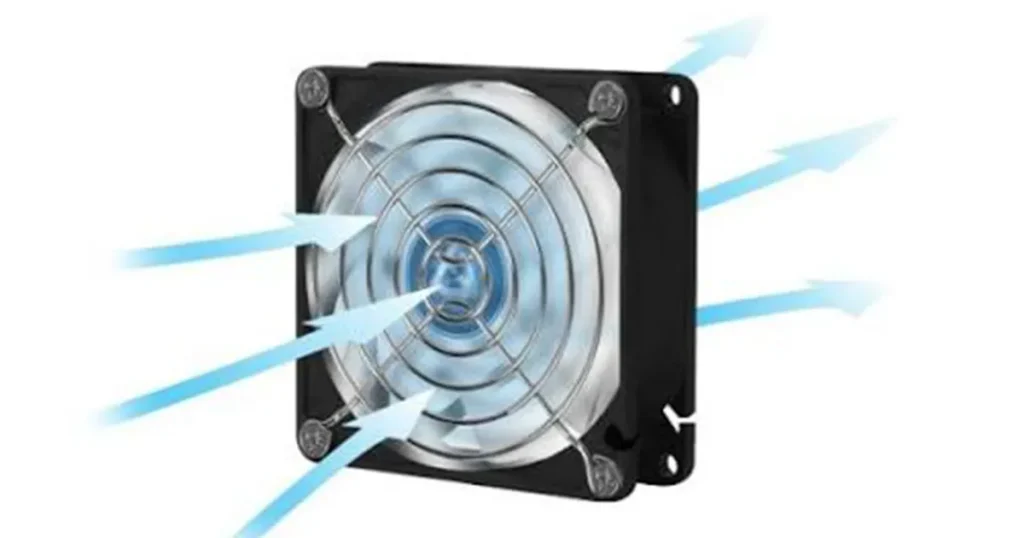
What counts as a fan guard?
| Accessory | Primary function | Typical airflow concern |
|---|---|---|
| Wire finger guard | Reduce access to rotating blades | Wire wakes and close spacing near the blade tips |
| Molded plastic grille | Guarding, appearance and mounting integration | Thick ribs, central blockage and abrupt edges |
| Louvered cover | Guarding and directional or weather protection | Turning loss and reduced free area |
| Perforated sheet | Integrated enclosure protection | Hole size, sheet thickness and low open area |
| Fine mesh or screen | Foreign-object or insect control | High velocity through small openings and rapid fouling |
| Filter guard assembly | Particle filtration plus access protection | Filter media usually dominates clean and loaded pressure drop |
A finger guard and an air filter are not interchangeable. A guard limits physical access; a filter captures particles. Adding fine mesh to improve particle protection can turn a low-loss guard into the main restriction in the system.
How a guard changes the fan operating point
A fan operates where its pressure-flow curve meets the resistance curve of the installed air path. Adding a guard raises resistance. The new intersection usually moves toward lower airflow and higher fan pressure.
The guard does not consume a fixed number of CFM. Pressure loss changes with airflow velocity and geometry. A useful simplified relationship for many local restrictions is:
Guard pressure drop (Pa) = loss coefficient x air density x velocity^2 / 2
The loss coefficient must come from measured data or a defensible geometry model. It should not be guessed from appearance. Velocity should be based on the relevant flow area, not automatically the outside dimensions of the fan frame.
An official axial-fan technical reference shows that fitting a guard grille changes both pressure-flow performance and efficiency. The result depends on guard geometry and operating flow.
Note: A fan’s catalog airflow may have been measured without your guard, grille or enclosure panel. Confirm the published test configuration before attributing the installed loss to the fan.
Why open-area percentage is not enough
Two covers can both claim 80% open area and create different pressure loss. A cover with many small holes has more wetted edge and may behave differently from a wire guard with a similar total opening. Thick perforated material creates short passages rather than ideal zero-thickness holes.
The airflow also needs room to contract and expand through the openings. When a grille sits very close to rotating blades, wakes from ribs interact with the blade-passing flow. This can add tonal noise even if the measured airflow loss is modest.
Check these details together:
- net free area and how it was calculated;
- wire, rib or hole geometry;
- center-hub blockage;
- distance from the rotating impeller;
- alignment of ribs with blade motion;
- edge shape and surface condition;
- whether mesh or filter media is also present; and
- expected contamination loading.
Inlet and outlet guards do not behave identically
A guard at the fan inlet
Air approaching an axial fan should be as uniform as practical. A close or asymmetric inlet guard can create wakes before the blades, starve one region of the inlet and increase interaction noise. A large central obstruction or nearby wall can compound the effect.
If the guard is part of a removable filter frame, its distance and sealed perimeter matter. Air that bypasses the filter or enters around the fan frame can make a measurement look better while weakening contamination control.
A guard at the fan outlet
Flow leaving an axial fan contains swirl and an uneven velocity profile. A close outlet guard sits in that disturbed flow. Rib orientation and distance can change noise, pressure recovery and local recirculation.
Do not assume moving the same guard from inlet to outlet keeps performance unchanged. Test the final orientation. The related fan inlet clearance guide explains how nearby obstructions change the approach flow.
Which guard design is likely to create less restriction?
At equal safety performance, a well-spaced wire guard often has less resistance than a thick, low-open-area molded grille or fine perforated sheet. That is a screening observation, not a universal ranking.
| Design choice | Possible benefit | What still needs validation |
|---|---|---|
| Higher effective free area | Lower average velocity through openings | Safety access and structural strength |
| Thinner, rounded wires or ribs | Smaller wakes | Durability and corrosion resistance |
| More clearance from blade tips | Reduced blade-wake interaction | Available installation depth |
| Balanced, symmetric pattern | More uniform flow | Actual pressure drop and tone |
| Larger outlet opening | Lower discharge velocity | Enclosure rating and leakage path |
A general cooling-fan technical reference identifies filters as a major pressure-loss source and guards as another installation resistance. This is why the complete accessory stack should be evaluated rather than each part in isolation.
How to quantify the loss
Use the supplier’s pressure-drop curve when available
A curve relating pressure drop to airflow is more useful than one free-area number. Make sure the curve applies to the exact guard, orientation and test condition.
Add the guard to the system curve
Combine guard loss with filters, louvers, heat exchangers, internal restrictions and outlet losses. Then find the new intersection with the fan curve. Do not subtract a guessed percentage from free-air CFM.
Run an A/B test in a controlled fixture
Measure the fan at the required operating point with and without the guard while keeping speed, voltage, density and test setup unchanged. Record airflow, static pressure, input power and sound if noise matters.
Verify the actual enclosure
A controlled fixture isolates the accessory loss; an enclosure test shows whether the equipment still meets its thermal limit. Both are useful because local component layout may produce effects that a simple guard test cannot reproduce.
Follow standardized fan-performance methods where a formal rating is required. For prototype decisions, document the measurement plane, instruments, accessory stack and uncertainty so the comparison can be repeated.
Noise can change before airflow becomes unacceptable
A guard creates wakes. When those wakes repeatedly meet rotating blades, they can create a distinct tone related to blade-passing frequency. The sound may be more objectionable even if the overall dBA change appears small.
If a new guard causes a whine or tonal peak:
- confirm that no wire or cable touches the frame;
- check that the guard is flat and fasteners are evenly tightened;
- increase blade-to-guard distance if the design allows;
- compare inlet and outlet placement;
- inspect rib symmetry and central obstruction; and
- measure at the same fan operating point, not only the same voltage.
Reducing fan speed can lower noise, but it also moves the operating point. Confirm airflow and component temperature after any control change. See axial fan noise reduction for wider acoustic checks.
Safety and enclosure protection remain controlling requirements
A lower-loss guard is useful only if it provides the required protection. Applicable product standards, risk assessment, access openings, probe requirements, material, flame behavior and impact resistance may affect the design.
Adding or changing a guard, louver or filter frame can also affect the completed enclosure’s ingress protection. Do not assume the fan’s IP rating transfers to a panel opening or accessory assembly.
Keep loose wires, insulation, labels and hardware away from the impeller. Isolate power before removing a guard for service. Where maintenance staff can reach the fan, design the service procedure around the actual hazard rather than relying on a warning label.
A practical guard-selection checklist
- Define the required contact and foreign-object protection.
- Obtain the exact fan curve and its test configuration.
- Identify every inlet and outlet accessory in the final assembly.
- Compare pressure-drop data at the target airflow.
- Check blade-to-guard clearance and mounting tolerance.
- Evaluate tonal noise as well as broadband dBA.
- Test clean and expected contaminated conditions.
- Verify component temperatures in the complete equipment.
- Confirm the final enclosure and safety requirements.
What LINKWELL needs to review the installation
Provide the LINKWELL fan model, operating voltage, required airflow and pressure, guard drawing, filter or screen details, distance from the fan, panel cutout and available installation depth. Include photos or a section drawing if the guard is integrated into a cabinet wall.
LINKWELL can help compare compatible axial fan and accessory options. Final performance must still be validated in the equipment because surrounding geometry determines the installed operating point.
Related pages include axial fan accessories, wire fan guards and how to read a fan curve.
Frequently asked questions
How much airflow does a fan guard reduce?
There is no fixed percentage. The result depends on guard geometry, velocity, position, distance from the blades and the fan’s operating point. Use pressure-drop data or an A/B test.
Is open-area percentage enough to compare guards?
No. It is useful for screening, but hole or wire shape, material thickness, spacing and blade interaction also affect pressure loss and noise.
Should a finger guard go on the inlet or outlet?
Install guarding wherever the risk assessment requires it. If either position is acceptable, compare airflow and sound in the final arrangement because inlet and outlet effects differ.
Does a filter count as a fan guard?
A filter may be part of a guarded assembly, but filtration and contact protection are different functions. Confirm both requirements separately.
Can I remove the guard to increase airflow?
Not where the guard is required for safety or foreign-object protection. Reduce restriction through a better guard, larger opening, lower velocity or revised installation instead.
Why did the fan become louder after adding a grille?
The grille may create wakes close to the blades, add resistance or excite the panel. Check spacing, rib geometry, mounting and the new operating point.

