
A prototype cools the enclosure correctly, but the first production units run a few degrees warmer. The fan label and part number have not changed, so it is tempting to blame the fan immediately. Sometimes unit-to-unit airflow variation is involved. Just as often, the real cause is a different filter, grille, supply voltage, test method, air density, or operating point.
That is why cooling fan airflow tolerance cannot be handled as a percentage printed beside a free-air value. A useful tolerance must identify what is being measured, where the fan operates on its curve, how the measurement is made, and which system conditions are held constant.
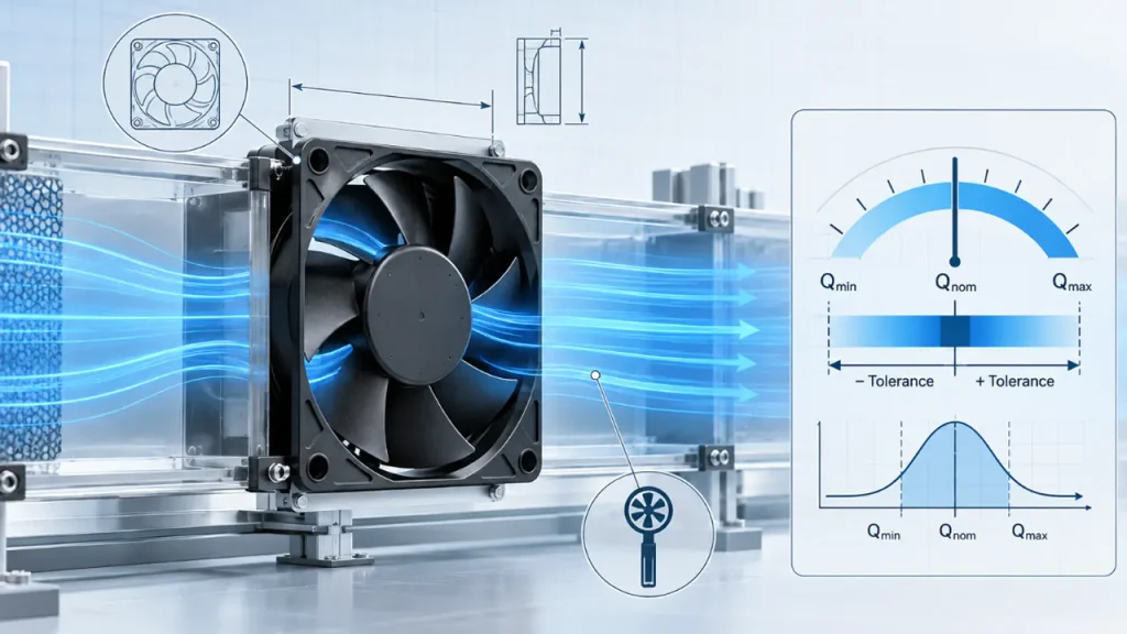
What Does Cooling Fan Airflow Tolerance Mean?
Cooling fan airflow tolerance is the permitted difference between a declared airflow value and the airflow verified under agreed conditions. It accounts for normal variation in fan production and measurement, but it does not make every installation effect part of the fan tolerance.
For example, a fan can meet its own performance requirement on a controlled test setup and still deliver less airflow in an enclosure with a restrictive filter. The lower installed airflow is then a system result, not automatically a nonconforming fan.
This distinction matters in OEM projects. The supplier controls the fan construction and declared fan data. The equipment designer controls much of the air path, including guards, vents, filters, heat exchangers, cables, spacing, and leakage paths. The acceptance plan needs to separate those responsibilities.
Note: A tolerance only has meaning when it is tied to a stated operating point and test condition. “Airflow must be within 10%” is incomplete if it does not say whether the value is free-air flow, a point on the pressure-flow curve, or airflow measured inside the finished equipment.
Nominal Airflow, Tolerance and Guaranteed Performance Are Not the Same
These terms are often mixed together during sourcing, yet they answer different questions.
| Term | What it tells you | What it does not tell you |
|---|---|---|
| Nominal airflow | A stated reference value under specified conditions | The exact airflow of every production unit in every installation |
| Airflow tolerance | The permitted deviation from the declared value under an agreed method | Whether the equipment will meet its temperature limit |
| Fan curve | How airflow changes as pressure resistance changes | The actual operating point until the system resistance is known |
| Equipment airflow requirement | The flow needed through the intended thermal path | Which fan will produce it without pressure and installation data |
| Guaranteed or acceptance value | A contractually agreed performance condition and acceptance rule | A universal tolerance that applies to every fan model |
A datasheet value is therefore a starting point, not a complete incoming-inspection specification. Before treating it as an acceptance limit, check the rated voltage, speed, air density, test configuration, pressure condition, and whether the value is typical, nominal, minimum, or guaranteed.
Why Airflow Measurements Vary
If two readings do not match, the difference may come from the fan, the test, or the equipment. Finding the correct source is more useful than immediately tightening the tolerance.
Normal Unit-to-Unit Variation
Motor characteristics, electronic components, bearings, impeller geometry, assembly alignment, and friction all have manufacturing tolerances. These variations can change speed, power, pressure capability, and airflow slightly from one unit to another. The relationship is not always one-to-one: a small speed difference does not automatically prove the same percentage difference in installed airflow.
Supply Voltage and Control Signal
A DC or EC fan should be evaluated at its specified electrical condition. Voltage drop in a cable, current limiting during startup, an incorrect PWM signal, or a controller that never reaches the requested duty cycle can reduce speed. Measuring voltage only at the power supply can miss the drop at the fan connector.
When a fan has speed feedback, compare the measured speed with the model specification, but do not use speed alone as a substitute for airflow. A blocked air path can leave fan speed relatively stable while useful airflow through the target component falls.
Operating Point on the Fan Curve
The free-air rating is measured near zero external static pressure. Most real equipment does not operate there. Filters, grilles, heat sinks and internal passages create resistance, moving the fan to a different point on its pressure-flow curve.
A unit that appears acceptable in a free-air check may have too little pressure capability for the real system. Conversely, a fan with a lower free-air number can sometimes deliver more useful flow in a restrictive enclosure if its curve is better matched to the operating pressure. The article How to Read a Fan Curve explains how the system curve and fan curve determine that point.
Test Setup and Installation Category
Inlet and outlet conditions change fan performance. A straight test chamber, an open bench, a ducted outlet, and a finished enclosure do not present the same flow field. ISO 13348:2025 states that fan performance can vary considerably with installation category and treats the installation category as part of technical data presentation. That is an important warning against comparing numbers taken from different setups as though they were interchangeable. See the ISO 13348:2025 overview.
Air Density and Environmental Conditions
Temperature, altitude, humidity, and barometric pressure affect air density. For many compact cooling projects, temperature is the parameter noticed first, but altitude can also matter because a given volumetric airflow carries less mass of air at lower density. When measurements are compared between laboratories or locations, record the environmental conditions and the correction method instead of assuming that every CFM reading represents the same cooling capacity.
Measurement Method and Instrument Position
A handheld anemometer at one point in front of a fan does not normally measure total fan airflow. Velocity is not uniform across the outlet: the hub, frame struts, blade wake, swirl, and nearby obstacles create a nonuniform profile. A reliable airflow result needs a defined measurement area, sufficient sampling, suitable instrumentation, and a method appropriate to the expected flow.
If the purpose is equipment validation rather than fan laboratory testing, temperature rise and component temperature may be more meaningful acceptance measures. Airflow measurement can still help diagnose the system, but it should not replace the thermal requirement the airflow is meant to satisfy.
Airflow Tolerance Depends on the Operating Point
A single percentage around maximum airflow can hide the part of the curve that matters most. Consider two fans that both meet a free-air requirement. If the equipment has a dense filter and heat exchanger, their actual operating points may be quite different because their pressure curves have different shapes.
For that reason, a stronger specification identifies a required airflow at an expected static pressure. If the system resistance is not known yet, measure or estimate it before final fan approval. The result should be checked again after the production enclosure, guard, filter, and cable layout are available.
This also prevents a common sourcing error: replacing a fan with another model that has the same dimensions, voltage and advertised CFM but a weaker pressure curve. The replacement can pass a visual inspection and still allow component temperatures to rise.
How to Specify Cooling Fan Airflow Tolerance
A practical specification does not need to be complicated, but it should remove avoidable ambiguity.
Define the Fan and Electrical Condition
Record the exact model, rated voltage, voltage measured at the fan, frequency for AC models, PWM or analog control condition where applicable, and warm-up time. If the fan can operate at several speed commands, identify the command used for acceptance.
Define the Aerodynamic Condition
State whether the requirement applies at free air or at a specified static pressure. For equipment projects, the pressure-flow operating point is generally more useful. Also state the inlet and outlet arrangement so that the supplier and purchaser do not test different configurations.
Define the Reference Value
Clarify whether the reference is a nominal catalog value, a minimum value, a jointly approved golden sample, or a value established during design validation. A golden sample is useful for comparison, but it should not replace an objective measurement method or a written acceptance band.
Define the Acceptance Band
State the permitted lower and upper limits and how rounding is handled. Do not copy a generic percentage from another model or supplier. The band should reflect the fan design, test capability, equipment margin, and commercial agreement.
As a simple illustration, if an agreed reference value is 100 CFM and the contractual tolerance is plus or minus 10%, the numerical band is calculated as follows:
Lower limit = 100 x (1 – 0.10) = 90 CFM
Upper limit = 100 x (1 + 0.10) = 110 CFM
This example only shows the calculation. It does not recommend a 10% tolerance for LINKWELL products or for every cooling fan.
Define Sampling and Retest Rules
Specify the lot size, sample count, conditioning period, number of readings, and what happens when one sample is outside the limit. Without a retest rule, different teams may reach different decisions from the same data.
How to Verify Airflow Without Confusing Fan and System Problems
Start with the least intrusive checks. Changing several conditions at once may make the final result impossible to interpret.
- Confirm the model, revision, airflow direction, connector and wiring.
- Measure voltage at the fan terminals under steady operation.
- Confirm PWM, 0–10 V, or other control input against the model specification.
- Record fan speed when a valid tachometer or FG output is available.
- Inspect the inlet, outlet, guard, filter and heat exchanger for changes or blockage.
- Measure airflow using the same fixture and method used for the approved reference.
- Check component and exhaust-air temperatures in the finished equipment.
- Repeat the comparison with more than one fan before assigning the cause to an individual unit.
The guide How to Measure Fan Airflow covers measurement choices in more detail. When the laboratory result and installed result differ, also review fan system effects.
Airflow Tolerance vs Speed Tolerance
Speed tolerance describes variation in rotational speed under specified conditions. Airflow tolerance describes variation in aerodynamic output. They are related, but they are not interchangeable acceptance criteria.
A speed check is fast and useful for production screening. It can reveal the wrong voltage, control command, or motor behavior. It cannot show whether air is bypassing the heat sink, whether a filter has excessive pressure drop, or whether the enclosure creates inlet turbulence.
If the equipment depends on a minimum cooling result, use speed as one diagnostic signal and verify the thermal or airflow outcome separately. See Cooling Fan Speed Tolerance for the electrical and rotational side of the comparison.
Common Specification Mistakes
The most damaging mistakes are usually not calculation errors. They are missing conditions.
- Using maximum free-air CFM as the only requirement for a restrictive system.
- Comparing supplier data produced with different test arrangements.
- Setting a tolerance without defining whether it is typical, minimum, or guaranteed.
- Measuring voltage at the power supply instead of at the fan.
- Using a single-point air-velocity reading as total airflow.
- Rejecting a fan based on an enclosure test after the guard, filter, or vent geometry changed.
- Approving a replacement fan by size and free-air CFM while ignoring static pressure.
What OEM Buyers Should Request
For an early sample, request the fan curve, rated electrical condition, airflow direction, speed information, and relevant test basis. For production approval, add the agreed operating point, acceptable performance band, sample plan, and equipment-level thermal limits.
If the application is sensitive to small airflow changes, share the enclosure drawing, filter and grille information, heat exchanger pressure drop, target component temperatures, altitude, and control method. LINKWELL can then help narrow the fan selection and identify which measurements should be confirmed during prototype and production validation. The final acceptance values must still be tied to the selected model and agreed test conditions.
Frequently Asked Questions
Is cooling fan airflow exactly the same for every unit?
No. Normal manufacturing and measurement variation means individual units will not produce perfectly identical readings. The acceptable range must be defined for the particular model and test condition.
Does a stated CFM value include a tolerance?
Not necessarily. Check whether the datasheet identifies the value as nominal, typical, minimum, or guaranteed and whether a tolerance or rating method is stated.
Can speed tolerance be used as airflow tolerance?
No. Speed can support diagnosis and production screening, but airflow also depends on fan aerodynamics, system resistance and installation conditions.
Should airflow be checked at free air or at static pressure?
Free-air testing can be useful for a controlled fan comparison. For equipment selection and cooling validation, airflow at the expected operating pressure is usually more meaningful.
Why does the installed airflow differ from the catalog value?
The catalog value may be based on a different pressure or installation condition. Filters, guards, heat sinks, restricted clearances, air leakage and recirculation can all move the installed operating point.
What is the best airflow tolerance for a cooling fan?
There is no single percentage that is best for every fan. The tolerance should be agreed for the model, operating point, test method, equipment margin and production requirement.

