
The fan reaches its specified speed, the catalog curve looks adequate, and the enclosure still runs hot. This is a common point where a team suspects a bad fan. The real problem may be the way air enters and leaves the fan after installation.
Fan system effect is the performance penalty created by non-uniform, swirling or obstructed airflow close to the fan. It is not the same as the calculated resistance of a filter, heat sink or duct. It is an additional installation loss caused by a geometry that prevents the fan from operating like it did during its rating test.
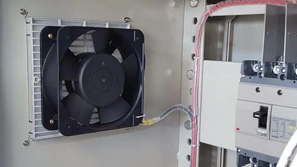
What Is Fan System Effect?
Fan curves are measured in a defined test arrangement. The inlet flow is controlled, the outlet condition is known, and the measurement setup is designed to produce repeatable data. In real equipment, the fan may sit against a wall, behind a perforated panel, beside a sharp elbow or directly in front of a cable bundle.
Those features can create swirl, separation and an uneven velocity profile. Part of the fan wheel works harder than the rest, the outlet cannot recover pressure effectively, and the installed operating point shifts. The fan may then deliver less airflow, more noise and more vibration than the catalog curve suggests.
AMCA’s technical guidance on system effect identifies adverse inlet and outlet flow conditions, obstructions, duct configuration and unaccounted accessory losses as common causes.
System Effect vs Normal System Resistance
| Condition | What causes it | How it appears |
|---|---|---|
| Normal system resistance | Filters, grilles, heat exchangers, ducts and flow passages | A predictable system curve that rises as airflow increases |
| Fan system effect | Poor flow quality or geometry immediately near the fan | An extra performance loss not represented by the ideal fan curve |
| Blocked or dirty system | Clogged filter, closed damper or foreign material | A changed system resistance that may worsen over time |
The distinction matters because installing a larger fan may not fix a bad inlet. It can increase local velocity and turbulence, making noise and system effect worse. First correct the air path, then decide whether the fan needs more pressure capability.
Common Causes at the Fan Inlet
A wall or panel too close to the inlet. Air must turn sharply into the fan, so the blade tips and hub do not receive a uniform flow. This is common when a fan is mounted close to an internal door, PCB or cable tray.
An elbow or side entry immediately before the fan. The flow reaches one side of the impeller faster than the other and may carry swirl into the blades.
A guard, filter or grille with poor open area. These parts create legitimate pressure drop, but uneven patterns or very close spacing can also distort the velocity profile. The combined penalty can be larger than the accessory’s standalone pressure drop.
Upstream fans or rotating equipment. Pre-swirl may assist or oppose the fan rotation. Either case changes the curve from the rating condition.
The detailed fan inlet clearance guide explains how to inspect the immediate approach path.
Common Causes at the Fan Outlet
An axial fan discharges a rotating, non-uniform jet. If the outlet is blocked by a wall, sharp grille or immediate 90-degree turn, velocity energy is lost before it can become useful pressure. A centrifugal fan can have an especially uneven outlet profile if ductwork begins with the wrong transition or elbow.
Short, abrupt expansions and contractions add separation. A damper, louver or dense guard installed directly at the discharge can create local recirculation. Increasing fan outlet clearance, using a smoother transition or relocating the obstruction often recovers airflow without changing the motor.
Tip: Before increasing fan speed, temporarily remove or move one nearby obstruction at a time. A large airflow or noise change identifies an installation loss that more RPM would only mask.
What Does System Effect Do to the Equipment?
The first symptom is usually less delivered airflow. Component temperature rises even though fan speed and current appear normal. The disturbed flow can also increase broadband noise, blade-pass tones and vibration. In severe cases, the fan operates near an unstable part of its curve and airflow begins to pulse.
Higher speed is a costly workaround. Under the fan affinity laws, power rises much faster than airflow when speed increases. The extra speed can also raise bearing load, noise and electrical demand while leaving the root cause in place.
How to Diagnose Fan System Effect
- Confirm rotation direction, airflow direction, RPM, voltage and control input.
- Compare free-air airflow with installed airflow using the same measurement method.
- Inspect the inlet and outlet for close walls, elbows, cables, guards and abrupt transitions.
- Measure pressure on both sides of filters and other known restrictions.
- Use safe airflow visualization or a grid of velocity readings to find swirl and non-uniform flow.
- Modify one feature at a time and record airflow, pressure, noise and component temperature.
Do not rely on a single handheld velocity reading at a turbulent fan outlet. The velocity profile may be highly uneven. Use an appropriate traverse, a defined test duct or another method suited to the installation. The guide on measuring fan airflow covers the measurement choices.
How to Reduce System Effect
Give the inlet a clear, symmetric approach and separate the fan from sharp turns where space allows. Use gradual transitions instead of sudden area changes. Improve grille open area, straighten cable routing and include the real filter, guard and louver losses in the system calculation.
At the outlet, provide room for the jet to develop before forcing it through a turn or obstruction. Baffles or straighteners can help in some systems, but they also add resistance and must be tested. Compact enclosures rarely have the ideal straight duct lengths used in laboratories, so practical improvement comes from comparing several layouts in the real package.
How to Prevent the Problem During Fan Selection
Select the fan against the complete system curve, not only a free-air CFM value. Share the inlet geometry, outlet geometry, filter, guard, heat exchanger and available clearances with LINKWELL. A higher-pressure fan may be appropriate for a restrictive package, but the layout should still avoid avoidable system effect.
Prototype testing should use production-intent panels, accessories and cable routing. Validate the hottest component temperature at the lowest expected fan performance and worst filter condition.
Frequently Asked Questions
Is fan system effect the same as pressure drop?
No. Pressure drop is the resistance of known components and passages. System effect is an additional loss caused by unfavorable flow conditions near the fan.
Can system effect make a fan louder?
Yes. Turbulence, swirl and uneven blade loading can increase broadband noise, tones and vibration.
Will a higher-RPM fan solve system effect?
It may recover some airflow, but it also increases power and noise and may worsen the disturbed flow. Correct the installation first.
Does system effect apply to compact axial fans?
Yes. A close wall, guard, filter, cable bundle or abrupt outlet can reduce the installed performance of a compact axial fan.
How can I compare a fan curve with installed performance?
Use the same airflow and pressure definitions, account for accessory losses, and measure at a valid location. Then compare the installed operating point with the curve’s stated test condition.

