
Cooling fans can use compact wire-to-board plugs, multi-pin equipment connectors, terminal connections, or bare wire leads. The right choice depends on more than the plug’s appearance. It must match the fan voltage, wire functions, connector series, pin count, pitch, keying, terminal size, current rating, and the mating part already used in the equipment.
This distinction matters during replacement and OEM sourcing. Two connectors can look almost identical but have different pitches or locking features. Two four-pin connectors can also carry completely different signals. A connector is only compatible when the mechanical interface, electrical pinout, and operating requirements all agree.
What Is a Cooling Fan Connector?
A cooling fan connector is the interface between the fan lead wires and the equipment’s power or control circuit. On a simple fan, the connection may carry only supply and return. On a monitored or speed-controlled fan, the same harness may also carry a tachometer signal, PWM input, alarm output, or another model-specific function.
The complete connection normally includes more than the visible plastic housing. It may involve crimp terminals, a receptacle housing, a PCB header or wire-to-wire mate, wire seals, a latch, and strain relief. If any one of these parts is wrong, the connector may not mate correctly or may make an unreliable electrical contact.
Note: Connector type and wire count are not the same thing. A four-wire fan describes the number of conductors and available functions. A connector family describes the mechanical parts used to terminate those conductors.
Common Cooling Fan Connector Types
There is no single connector used by every cooling fan. Product size, fan current, available PCB space, service requirements, production volume, and the equipment environment all influence the choice.
Compact Wire-to-Board Plug Connectors
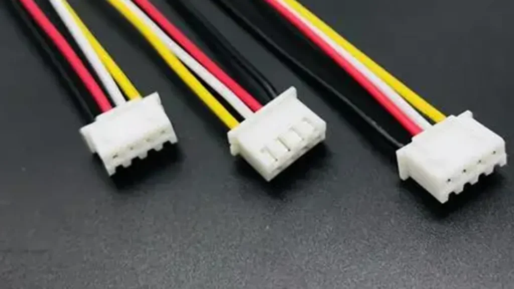
Compact crimp connectors are common on DC fans installed near a PCB, power module, display, controller, or embedded computer. A receptacle on the fan harness mates with a header on the board. The housing may use friction, a positive latch, or another polarization feature to reduce incorrect insertion.
Small white housings are often described with informal family names, but appearance is not a reliable identifier. Connector series, pitch, circuit count, header orientation, terminal, housing and mating part all matter. Two wire-to-board plugs with the same pin count can use different pitches, latches or terminal geometry, so an OEM drawing should specify the exact part number or include the mating sample.
This style works well when assembly speed and a compact PCB connection matter. It is not automatically suitable for every fan current or vibration level. The chosen series and terminal must be checked against the actual wire gauge, current, temperature and mating-cycle requirements.
Multi-Pin and PC-Style Fan Connectors
Three-pin and four-pin fan plugs are familiar in computers, servers and some electronic equipment. A common four-wire DC arrangement uses supply, ground, tachometer feedback and a PWM control input. However, a housing with four positions does not prove that the fourth pin is PWM, and a similar-looking connector may use a different pin order.
Market terms such as “fan plug” or “computer-style connector” are often used loosely. They may describe a general shape rather than an exact connector series. An OEM specification should identify the housing, crimp terminal, mating header, pitch and pin map instead of relying on a generic connector name.
Multi-pin plugs are useful when power and control signals need one detachable interface. They can make fan replacement faster, but only when the host header, pin assignment and control circuit are confirmed together.
Terminal Block Connections
Industrial control cabinets, power supplies and machinery often bring fan leads to a terminal block instead of a dedicated fan plug. The fan may arrive with bare, stripped, tinned or ferrule-terminated wires. This approach is practical when field wiring, maintenance access or integration with an existing control panel is more important than a compact PCB connection.
Terminal blocks also make it easier to separate power conductors from optional signal wires. The tradeoff is that installation becomes more dependent on correct stripping length, terminal torque, conductor identification and cable routing. A field technician must have a verified wiring diagram; wire color alone is not enough.
Bare Wire or Flying Leads
Bare wire leads give an OEM freedom to terminate the fan inside its own harness, controller or terminal system. Common requests include a specified lead length, stripped ends, tinned ends, ferrules, crimp terminals or individual labels.
This option is flexible, but “bare wire” is not a complete purchasing specification. The drawing should state conductor count, wire gauge, insulation type where relevant, finished lead length, strip length, end treatment and pin-function identification. Without those details, two batches can be electrically correct yet difficult to assemble consistently.
Locking or Sealed Connectors
Equipment exposed to vibration, dust, moisture or frequent service may need a connector with a positive lock, secondary retention, strain relief or environmental sealing. These features can help the connection remain secure, but they do not automatically give the whole fan assembly an IP rating. The connector, wire entry, fan construction and final equipment installation must be evaluated as a system.
Availability depends on the fan model and project requirements. A sealed connector also requires the correct mating half, seals, terminals and assembly process. Substituting only the visible housing may defeat the intended protection.
Cooling Fan Connector Types Compared
| Connection approach | Typical use | Main benefit | Important check |
|---|---|---|---|
| Compact wire-to-board plug | PCB, controller and embedded equipment | Small and quick to assemble | Exact series, pitch, terminal and header |
| Multi-pin equipment plug | Power plus feedback or control signals | Several functions in one detachable connection | Pin order, logic levels and mating part |
| Terminal block connection | Control cabinets and industrial machinery | Convenient field wiring | Wire preparation, identification and terminal rating |
| Bare wire or flying leads | OEM harnesses and custom equipment | Flexible integration | Length, gauge, strip and end treatment |
| Locking or sealed connector | Vibration or harsh-environment projects | Improved retention or connection protection | Complete mating set and environmental validation |
None of these options is universally best. A compact plug may be ideal inside a controller, while bare leads may be easier to integrate into an industrial cabinet. The correct choice is the one that fits the equipment interface and remains reliable under the real electrical, mechanical and environmental conditions.
2-Wire, 3-Wire and 4-Wire Fan Connectors
Wire count usually tells you how many electrical paths are available, not which connector family is fitted. For common low-voltage DC cooling fans, the following arrangement is widely used:
| Fan wiring | Typical functions | What the equipment can do |
|---|---|---|
| 2-wire | Supply and ground | Power the fan; model-specific voltage control may be possible |
| 3-wire | Supply, ground and FG or tachometer output | Power the fan and monitor speed |
| 4-wire | Supply, ground, FG or tachometer, and PWM input | Power, monitor and command speed through a separate control input |
This is a useful starting point, not a universal pinout. A third wire can be an alarm output rather than tachometer feedback. A fourth conductor may serve another control or status function. AC and EC fans can use different supply, grounding and control arrangements, so the DC convention must not be copied blindly.
For a deeper explanation of common DC wire functions, see DC Axial Fan Wiring: 2-Wire, 3-Wire and 4-Wire Fans.
Common Cooling Fan Connector Pin Functions
Power Supply
The power conductor carries the fan’s specified input voltage. On a DC fan, this is normally the positive supply. On an AC fan, the supply connection is line and neutral rather than positive and negative. Some EC fans accept AC input, while others use DC input; the model wiring diagram determines the correct arrangement.
Confirm nominal voltage, permitted operating range, frequency for AC models, polarity for DC models, and the maximum input current. The connector and contacts must be suitable for the conductor size and actual electrical load, including startup behavior where applicable.
Ground, Return or Protective Earth
A low-voltage DC fan usually has a negative return conductor. This must not be confused with protective earth. Depending on construction and safety requirements, an AC or EC fan may have a separate protective-earth connection. The datasheet and equipment wiring rules take priority over any color convention.
FG or Tachometer Signal
An FG or tachometer output sends pulses that the host controller can use to estimate fan speed or detect an abnormal condition. The signal type, number of pulses per revolution, pull-up arrangement and acceptable voltage depend on the fan electronics. Connecting the tach wire to an incompatible input can produce no reading or an incorrect reading even when the fan itself runs normally.
See Fan Tachometer Signal: How FG Speed Feedback Works for signal interpretation and validation.
PWM Control Input
A PWM input allows a compatible controller to request fan speed without repeatedly switching the main fan supply. The required PWM frequency, logic level, duty-cycle behavior and response at the minimum command are model-specific. A four-pin plug does not by itself confirm compatibility.
With a dedicated fourth-wire control interface, the fan receives steady supply power while a separate PWM input requests speed. This is electrically different from switching the main supply to a two-wire fan. For LINKWELL product selection, confirm the individual model PWM frequency, logic level, duty-cycle response, drive requirement and minimum-speed behavior.
RD or Alarm Output
An RD or alarm conductor can report a stopped or abnormal fan condition to the equipment controller. It is not automatically the same as an FG signal. FG provides a pulse train related to rotation, while an alarm output may change state when a defined condition occurs. The host input circuit and alarm logic must match the fan specification.
A connector can also carry model-specific analog control, communication or sensor signals. Never assign a function from wire color, connector shape or pin count alone.
Connector Type Does Not Determine the Fan Control Method
A frequent sourcing mistake is to treat connector shape as proof of electrical function. A four-position housing may contain only three terminals. A four-wire harness may use PWM, an alarm output or another model-specific signal. A three-wire fan may provide tachometer feedback, but another three-wire model may use a different third-wire function.
The same issue appears when replacing a fan. The new plug may physically fit the old header while supply polarity or signal positions are different. Physical mating is only the first compatibility check. Full compatibility requires the same voltage, pin assignment, signal type and control behavior.
Tip: Approve a connector by exact part number and pin map, not by a front-view photo. Ask for the housing, terminal and mating-header information when the connection is important to production.
If the application requires a dedicated PWM input, compare the connector drawing and control specification with the equipment header. The 4 Pin PWM Fan page explains the product-selection side of that interface.
How to Choose the Right Cooling Fan Connector
1. Confirm the Fan Power Requirement
Start with the fan type and supply: AC, DC or EC; rated voltage; operating range; frequency where relevant; running current; and startup demand. Do not select a small connector only because it fits the available space. Contact, terminal and wire ratings must suit the load and operating temperature.
2. Define Every Required Signal
Decide whether the equipment needs fixed-speed operation, speed feedback, PWM control, an alarm output or another interface. This determines the required conductor count, but it still does not determine the connector series. Document each signal name, direction and electrical requirement.
3. Identify the Mating Connector
If the equipment already has a PCB header or harness plug, record its manufacturer, series and part number. Confirm whether the fan side needs a receptacle or plug, and check the terminal and wire-seal part numbers. “Male” and “female” can be ambiguous because people may describe the housing or the metal contact, so part numbers and drawings are safer.
4. Check Pitch, Pin Count and Keying
Measure pitch from the center of one contact position to the center of the next, but do not use pitch as the only identifier. Housing width, latch style, polarization ribs, pin shape, entry direction and circuit count must also agree. A forced connection can deform contacts or create intermittent operation.
5. Confirm the Pin Map and Orientation
Create a pin-to-pin table showing the fan signal, wire color, connector cavity number and equipment header pin. State which view the drawing uses: mating face, wire-entry side or PCB side. Mirrored drawings are a common cause of reversed pin order.
6. Specify Wire Length, Gauge and Routing
Lead length should reach the mating point without tension and without leaving excess cable near the impeller or airflow path. Confirm finished length and tolerance, conductor size, insulation, sleeve or tie requirements, exit direction and any bend-radius or routing constraints.
7. Review the Installation Environment
Consider vibration, shock, temperature, humidity, dust, chemicals, service frequency and access. A friction-lock plug may be sufficient inside stationary electronics. Equipment with vibration or repeated maintenance may need positive latching, secondary retention or another robust connection. Environmental claims must be evaluated for the complete connector pair and finished assembly.
8. Validate Before Production
Do not release a custom harness from a photo and written description alone. Check samples against the actual mating connector. Verify continuity, pin order, polarity, fan startup, running current, feedback and control functions. Reconnect the interface several times and inspect terminal retention, latch engagement, cable strain and clearance from moving parts.
Where the application requires it, extend validation to temperature, vibration, humidity or other equipment-level tests. The test conditions should reflect the real installation rather than a generic connector claim.
Cooling Fan Connector Selection Checklist
| Item to confirm | Information needed | Why it matters |
|---|---|---|
| Fan input | AC, DC or EC; voltage; frequency; current | Prevents electrical mismatch |
| Wire functions | Power, return, FG, PWM, RD or other signals | Defines conductor count and host interface |
| Connector identity | Manufacturer, series and part number | Avoids look-alike substitutions |
| Mating part | Header or harness-mate part number | Confirms mechanical compatibility |
| Pin map | Cavity number, signal and drawing view | Prevents reversed polarity or signals |
| Lead specification | Length, tolerance, gauge, insulation and end treatment | Supports assembly and current requirements |
| Mechanical conditions | Latch, keying, strain relief, vibration and service access | Supports connection retention |
| Environment | Temperature, moisture, dust and chemical exposure | Defines protection and validation needs |
| Approval evidence | Drawing, sample and functional test result | Reduces production integration risk |
Custom Cooling Fan Connectors for OEM Projects
An OEM project may need more than a standard fan with a different plug. The connector decision can affect cable routing, assembly time, PCB layout, service replacement and control-system validation. It should be reviewed early, before the fan drawing and equipment harness are released.
To evaluate a custom connection, provide the fan size or candidate model, supply voltage, required airflow and static pressure, control or feedback functions, connector manufacturer and part number, mating-part information, pin map, wire length, conductor gauge and installation conditions. A dimensioned drawing or a physical mating sample is especially useful when the connector cannot be identified reliably.
As an industrial cooling fan manufacturer, LINKWELL can evaluate connector, wiring and signal requirements for OEM applications. Available connector and wiring options depend on the fan model, order requirements and confirmed project specifications. The engineering approval should identify exactly what will be supplied rather than promise that every connector is available for every model.
Common Mistakes When Selecting a Fan Connector
- Choosing by housing color or appearance without an exact series and part number.
- Assuming an informal connector name refers to one universal series.
- Matching pin count but not matching the pin functions or sequence.
- Treating wire colors as a universal standard.
- Confusing tachometer feedback with PWM control or an RD alarm output.
- Ignoring the mating header, crimp terminal or wire-seal specification.
- Using a connector or wire gauge without checking current and temperature conditions.
- Forgetting lead-length tolerance, exit direction and cable clearance.
- Assuming a sealed plug makes the entire fan installation waterproof.
- Approving a custom harness without a sample fit and functional test.
Most connector failures begin as specification failures. A clear drawing, pin map and approved mating sample are more valuable than a long list of informal connector names.
Frequently Asked Questions
What connector is used for a cooling fan?
Cooling fans may use compact wire-to-board plugs, multi-pin equipment connectors, terminal-block leads, bare wires or locking and sealed connectors. There is no single connector for all fans. The correct interface depends on the fan type, supply voltage, current, signal requirements, equipment header and installation environment.
What is the difference between a 2-wire, 3-wire and 4-wire fan connector?
In a common DC fan arrangement, two wires supply power and ground, a third adds FG or tachometer feedback, and a fourth adds a separate PWM control input. These functions are not universal. The datasheet or approved wiring drawing must confirm the actual assignment for the selected fan.
Are cooling fan connectors standardized?
Some applications use widely recognized connector families and interface conventions, but cooling fan connectors are not universally interchangeable. Series, pitch, latch, keying, terminal, pin order and signal behavior can vary. Even physically mating connectors may not be electrically compatible.
Does a 4-pin fan connector always mean PWM?
No. A common four-wire DC fan uses supply, ground, tachometer feedback and PWM control, but four positions or four conductors do not guarantee that arrangement. A model may use an alarm output, analog input or another function. Check the pin definition and control specification.
Can I change the connector on a cooling fan?
A connector can be changed when the replacement housing, terminals, wire size, pin map and mating interface are compatible. Re-termination must maintain correct polarity, signal integrity, insulation and terminal retention. For production equipment, use an approved drawing and controlled crimping process rather than a field guess.
Can wire color identify the fan pinout?
Wire color can be a useful label, but it is not reliable proof of function across different manufacturers or models. Confirm every conductor with the model datasheet, wiring diagram or approved sample. This is especially important for tachometer, PWM and alarm lines.
What information is needed for a custom fan connector?
Provide the fan model or size, supply voltage, connector series and part number, mating part, pin configuration, wire functions, finished lead length, wire gauge, required control or feedback signals and installation environment. Include drawings or samples if the connector identity is uncertain.
Can LINKWELL customize fan wire length and connectors?
LINKWELL can evaluate connector, lead and signal requirements for OEM cooling-fan projects. Feasibility depends on the selected fan model, electrical interface, component availability, project quantity and validation requirements. Share the mating-connector information and wiring drawing so compatibility can be reviewed before production.
Final Selection Advice
Choosing among cooling fan connector types is not simply a matter of finding a plug that fits. Start with the electrical functions, identify the exact connector and mating parts, document the pin map and wire specification, and validate the assembled interface in the real equipment.
For an OEM review, send LINKWELL the fan requirements, connector part number, mating-header information, wire length, pin configuration and any PWM, FG or RD needs. A clear interface specification makes fan selection faster and reduces wiring changes when the equipment reaches production.

