
A two-wire fan is connected during a prototype build, but the red and black leads have been swapped. Nothing turns. After the wiring is corrected, the fan starts normally. Was the fan protected, or was the team simply lucky?
Reverse polarity protection is a circuit or design feature intended to prevent damaging reverse current when the positive and negative DC power connections are exchanged. Depending on the design, the fan may block current or isolate its internal electronics until correct polarity is restored.
The important limitation is that protection varies by model and wiring configuration. A protected two-wire power input does not automatically mean that PWM, FG, RD, enable or communication wires can tolerate an incorrectly referenced supply.
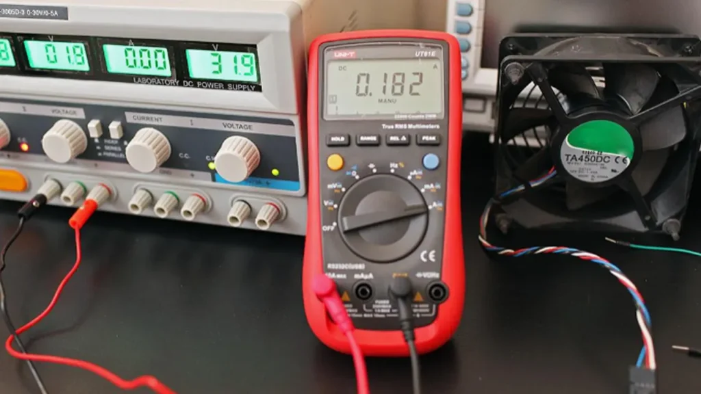
How Does Cooling Fan Reverse Polarity Protection Work?
A brushless DC fan contains electronic commutation circuitry. Semiconductor devices, capacitors and sensors inside that driver are polarity-sensitive. Applying the supply backward can create current paths that were never intended for normal operation.
A reverse polarity protection design interrupts or limits those paths. Common approaches include a series diode, a bridge arrangement, a MOSFET-based protection stage or protection integrated into the motor driver. The implementation affects voltage drop, heat, current capacity, cost and fault behavior.
From the equipment designer’s perspective, the exact circuit is less important than the guaranteed result and its conditions. The specification should state whether reverse connection is blocked, whether the fan recovers after correct wiring is restored, what voltage and duration are covered, and whether the statement applies only to the power leads.
Note: Reverse polarity protection is not universal. Confirm it for the exact LINKWELL model and wiring option before relying on it in equipment design.
What Happens Without Reverse Polarity Protection?
The outcome depends on the driver design, supply impedance and connection time. A fan may simply remain stopped, draw excessive current, heat an internal component, damage a protection diode or fail immediately. A current-limited bench supply can hide a problem that becomes destructive on a low-impedance battery or industrial DC bus.
Even when the fan appears to work after the leads are corrected, latent damage is possible. A stressed semiconductor or capacitor may pass a brief functional check but have reduced reliability. Do not approve a reversed unit for production use solely because it spins again.
The equipment can also be affected. A reverse-current path may pull down a shared rail, blow a fuse, damage a controller output or disturb other fans. Protection must therefore be considered at both the fan and system levels.
Why Multiwire Fans Need Extra Care
A two-wire DC fan has power and return. A three-wire fan usually adds speed feedback, while a four-wire fan can add a separate PWM command. Some industrial configurations also provide locked-rotor alarms, enable inputs or communication lines.
Those signal wires connect the fan to another circuit. If the fan supply is reversed while a signal line remains referenced to the equipment controller, current can flow through an input-protection diode, pull-up resistor, transistor or ground path. The power stage may have reverse protection while the signal interface does not.
| Connection | Normal purpose | Reverse-wiring concern |
|---|---|---|
| Positive supply | Powers the fan | Can be blocked by a model-specific protection stage |
| Power return | Completes the supply circuit | Incorrect reference can affect every signal line |
| FG or tach output | Reports speed pulses | External pull-up may create an unintended current path |
| RD or alarm output | Reports a fault or locked rotor | Controller reference may remain connected during the fault |
| PWM or analog input | Commands fan speed | Input circuitry may not tolerate a reversed power reference |
The cooling fan connector guide explains why pinout, wire color and connector keying must be approved together rather than assumed from the number of wires.
Reverse Polarity Protection Is Not the Same as Other Protection
Locked-rotor protection addresses a powered fan whose rotor cannot turn. It does not prove that the supply can be reversed.
Overcurrent protection limits excessive current under defined conditions. A fuse or electronic limiter may help at system level, but it does not automatically keep reverse voltage away from sensitive fan electronics.
Overvoltage protection addresses excessive voltage in the correct polarity. Reverse polarity is a different electrical stress.
Short-circuit protection protects a source or output against a low-resistance connection. It does not necessarily protect the fan when its input polarity is exchanged.
ESD and surge immunity address transient events. They should not be used as evidence for continuous or accidental reverse connection.
Keep these functions separate in the specification. The fan locked rotor protection guide explains the mechanical-stall case.
How to Check Whether a Fan Has Reverse Polarity Protection
Start with the exact datasheet, approved drawing or model specification. Look for terms such as reverse polarity protection, reverse connection protection or reverse-voltage protection. Then check the stated boundary.
- Which input wires are protected?
- What reverse voltage and duration are allowed?
- Must signal and control wires be disconnected?
- What current flows during reverse connection?
- Does the fan recover automatically after correct wiring is restored?
- Is protection guaranteed or described only as a typical behavior?
- Does the protection apply across the full operating temperature range?
If the feature is not stated, treat it as unconfirmed. Do not infer protection because the fan survived one accidental bench connection or because another model in the same family includes it.
How to Prevent Reverse Wiring in Production Equipment
Electrical protection is the last line of defense, not the preferred assembly method. Start with a polarized connector and a mechanical key that prevents incorrect mating. Define pin numbers on the drawing, control wire colors through the approved bill of materials, and inspect the harness before power is applied.
For custom harnesses, verify both ends. A connector can be correctly keyed while the terminals are inserted into the wrong cavities. Automated continuity and polarity testing is more reliable than visual color inspection alone.
The equipment power input may also use a fuse, current limit or protected high-side switch. Those devices should be sized for normal running and startup current so that fault protection does not create nuisance trips. See the fan power supply sizing guide for startup and source-capacity checks.
Tip: Put connector housing, terminal, pinout, wire color and cable length on the approved fan drawing. “Four-wire DC fan” is not a complete wiring specification.
How to Validate Reverse Polarity Protection Safely
Intentional reverse-polarity testing should be performed only by qualified personnel using a controlled test plan. Mains-powered AC and EC fans are outside the scope of a simple DC reverse-connection test.
- Confirm that the proposed fan specification permits the test and defines its limits.
- Use the exact production fan, cable, connector and controller interface.
- Start with a current-limited DC source and suitable monitoring.
- Define the reverse voltage, duration, temperature and state of every signal wire.
- Record reverse current, component heating and behavior of the shared power rail.
- Restore correct polarity and verify startup, speed, current, FG or RD output, PWM response, noise and temperature.
- Use an agreed acceptance criterion and quarantine samples exposed beyond the approved condition.
Do not use a battery, unrestricted high-current supply or improvised loose leads to discover the protection limit. The purpose of validation is to confirm a documented requirement, not to increase reverse voltage until the fan fails.
Selecting a Protected DC Cooling Fan
Reverse protection is one part of the selection. The fan must still meet voltage, airflow, static pressure, size, noise, temperature, startup current, control and alarm requirements. A protection feature does not compensate for inadequate cooling performance or an incompatible signal interface.
When requesting a LINKWELL recommendation, provide the nominal and maximum DC bus voltage, fan size, required operating point, connector pinout, cable length, PWM or feedback requirements and the reverse-polarity condition that the equipment must tolerate. LINKWELL will need to confirm the function for the proposed model and option.
Frequently Asked Questions
Will a DC fan spin backward if the polarity is reversed?
Normally, a brushless DC cooling fan will not simply run backward. Its electronic driver requires the correct supply polarity. The fan may remain stopped or be damaged, depending on its protection design.
Do all brushless DC fans have reverse polarity protection?
No. The feature and its limits vary by model. Check the exact specification.
Will a fuse protect a fan from reverse polarity?
Not necessarily. A fuse responds to current and may not open before polarity-sensitive electronics are damaged. Use documented fan and system-level protection.
Can reverse polarity damage the PWM or tachometer circuit?
Yes. Signal wires connected to an external controller can create current paths that bypass or fall outside protection on the power input.
Can I test protection with a bench power supply?
Only under a controlled procedure that matches the documented rating. Use current limiting, monitoring and the complete production wiring configuration.
Does LINKWELL provide reverse polarity protection?
Protection options depend on the exact DC fan model and configuration. Confirm the requirement during selection and include it in the approved specification.

