
A 24 V cooling fan can draw less than one amp during normal operation and still cause a 24 V control supply to shut down at startup. The problem is rarely solved by multiplying the label current by the number of fans and choosing the next larger wattage.
Fan power supply sizing has four separate checks: voltage compatibility, continuous load, startup peak and voltage at the fan connector. You also need to know how the supply responds to an overload. A supply that enters hiccup mode immediately can behave very differently from one that supports a short peak.
The sizing method below applies to compact DC cooling fans powered from an AC-DC or DC-DC supply. AC fans and AC-input EC fans must be handled according to their rated line supply and electrical documentation; do not connect them to a DC output because the wattage appears similar.
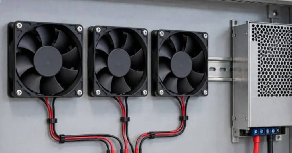
Collect the data before choosing the supply
Start with the exact fan order code, not only its frame size. Different speed, control and protection versions can draw different current.
| Input | Why it matters | Where to get it |
|---|---|---|
| Rated voltage and operating range | Defines acceptable steady and transient terminal voltage | Fan datasheet or approved drawing |
| Running current or input power | Sets continuous load | Model data at the required operating condition |
| Startup or inrush waveform | Sets short-duration peak requirement | Manufacturer data or measurement |
| Number of fans starting together | Determines simultaneous load | Equipment control sequence |
| Other loads on the supply | Prevents fans from consuming reserved capacity | System power budget |
| Cable and connector resistance | Determines voltage drop at the fan | Harness design and measurement |
| Ambient temperature and installation | May reduce available supply output | Power-supply derating curve |
| Fault and redundancy state | Defines the worst credible load | System safety and availability analysis |
If current is not provided but DC input power is known:
Fan current (A) = fan input power (W) / supply voltage (V)
Use electrical input power, not air power or motor output. If the fan has several speed settings, use the applicable maximum continuous electrical input for the circuit being designed.
Step 1: match the voltage range
A nominal 24 V label does not mean the fan will start and run correctly at every voltage that a nominal 24 V system can produce. Check the fan’s permitted operating range against the supply tolerance, cable drop and system transients.
The supply voltage at its terminals is only the beginning:
Fan terminal voltage = supply output voltage – distribution voltage drop
A controller, MOSFET, relay, fuse, connector and harness can each add resistance. The low-voltage condition is often most severe during startup, when current is highest.
Do not regulate fan speed by lowering the supply voltage unless the fan is approved for that method and the entire speed range has been validated. A PWM or analog control input may be the correct approach for compatible LINKWELL DC models.
Step 2: calculate continuous current
For fans connected in parallel to the same voltage supply:
Total fan running current = fan 1 current + fan 2 current + … + fan n current
Then include other continuous loads:
Total continuous load = total fan running current + other continuous current
The supply’s usable continuous output must exceed this load under the actual temperature, input voltage, mounting orientation and ventilation conditions. Read the supply derating curve. A unit rated at room temperature may deliver less inside a hot enclosure.
Avoid choosing a supply that runs continuously at its absolute limit. The required design allowance depends on supply guidance, load variation, measurement tolerance, expected additions and reliability objectives; it is not one universal percentage.
Step 3: check startup and inrush current
Startup is a separate pass/fail test. A fan can meet the continuous power budget and still fail to accelerate.
Peak load current = simultaneous fan startup current + other load current during that interval
Compare that value and its duration with the supply’s dynamic-load and overload specifications. Terms such as constant-current limiting, foldback, hiccup and peak-power mode describe different responses. If the supply voltage collapses and cycles, the fan may repeatedly restart.
The article on cooling fan startup current explains how to capture the fast inrush and longer acceleration current separately.
Step 4: calculate DC wiring voltage drop
For a two-wire power path:
Voltage drop (V) = current (A) x total loop resistance (ohm)
Total loop resistance includes the outgoing conductor, return conductor, contacts, protection devices, PCB traces and switches. Calculate the running drop and the startup drop. The latter can determine whether the fan starts reliably.
Long 12 V harnesses deserve particular attention because the same power requires twice the current of a 24 V system and four times the current of a 48 V system.
For a fixed electrical load:
Current (A) = power (W) / voltage (V)
This does not mean you can replace a 12 V fan with a 24 V or 48 V fan without redesign. Voltage must match the fan, controller, protection and connector system. See 24 V vs 48 V DC cooling fans for the system trade-offs.
Worked example: four 24 V DC fans
Assume an equipment design has four identical 24 V fans. The following values are illustrative, not LINKWELL model data:
- Running current per fan: 0.35 A
- Measured startup peak per fan: 0.75 A for the relevant interval
- Other continuous 24 V loads: 1.20 A
- All four fans can start together
Total fan running current = 4 x 0.35 = 1.40 A
Total continuous load = 1.40 + 1.20 = 2.60 A
Simultaneous fan startup current = 4 x 0.75 = 3.00 A
Peak system load during fan startup = 3.00 + 1.20 = 4.20 A
A 24 V, 3 A supply appears sufficient from the running load alone but does not cover the illustrative simultaneous peak. This does not automatically mean the correct selection is simply 5 A. You must check the supply’s allowed peak, duration, overload response, thermal derating and terminal voltage during the event.
If the controller starts two fans first and two later, the planned peak may fall. The fault case still matters: a blocked fan that repeatedly retries can overlap with a later start command.
Tip: Build a time-based load table for the first few seconds after power-on. It often reveals a peak that a static wattage total cannot show.
Multiple fans change more than the wattage
Fans are normally connected in parallel so that each receives rated voltage. Do not place nominally identical DC fans in electrical series to divide a higher supply voltage. Their electronic drives will not necessarily share voltage equally, especially during startup or fault conditions.
Give each branch appropriate conductor size, connector rating and protection. A single common fuse may remove all cooling after one wiring fault. Separate branch monitoring may improve diagnostics, but protection architecture must be based on the equipment’s safety and availability requirements.
For N+1 systems, include the electrical state after one fan or one supply channel fails. The remaining fan may be commanded to higher speed and draw more current. Review fan redundancy and failure testing before treating a spare fan as complete redundancy.
PWM control does not reduce the required supply voltage
A four-wire PWM DC fan generally receives a steady DC power supply while a separate signal commands speed. Do not reduce the supply rating in direct proportion to average PWM duty unless the fan documentation and measured input support that assumption.
The design must still accommodate full-speed operation, startup routines, fault commands and loss of the control signal. Confirm whether an open or invalid PWM input causes full speed, minimum speed or stop for the exact model.
If the host reads an FG output, check that the signal interface and fan power return are compatible. Power-supply noise or ground drop can affect both motor operation and feedback reliability.
Protection and grounding checks
The power supply must be coordinated with upstream protection, fan branch wiring and downstream electronics. Review:
- overcurrent and short-circuit behavior;
- fuse or breaker interrupting and time-current characteristics;
- reverse-polarity risk on DC fan branches;
- surge and transient environment;
- protective-earth requirements for the supply and enclosure;
- isolation requirements between control and power circuits; and
- the effect of one failed branch on the remaining cooling.
The fan’s internal locked-rotor or reverse-polarity protection does not replace equipment-level circuit protection. Confirm which functions are present in the selected order code rather than applying features from another model.
Validate the supply in the finished equipment
A successful bench calculation should be followed by an assembled-system test. Measure the fan-terminal voltage and supply output during cold startup, hot restart, minimum input line, maximum load and simultaneous fan command.
Then test abnormal conditions that the product safety plan allows: one fan disconnected, a stalled fan simulation, a blocked filter, loss of control signal and a rapid power interruption followed by restart. Monitor component temperatures as well as electrical values.
For production, define what gets verified. Connector polarity, supply voltage, fan rotation and FG feedback can often be checked without repeating a full engineering waveform test on every unit.
Information LINKWELL needs for fan and supply coordination
Provide the required fan size, voltage, airflow and pressure, number of fans, speed-control method, feedback signals, harness length, connector and ambient range. Also provide the intended power supply and startup sequence.
LINKWELL can then confirm suitable fan options and provide model-level electrical data for prototype validation. Final power-supply approval remains a system decision because the supply, wiring, controller and other loads are outside the fan boundary.
Related references include 12 V vs 24 V fans, DC axial fan wiring and cooling fan power consumption.
Frequently asked questions
What size power supply do I need for a DC fan?
Match the rated voltage, add continuous current for every simultaneous load, check startup peak and duration, include wiring drop, and apply the supply manufacturer’s temperature and installation derating.
Can I use a 24 V power supply for a 12 V fan?
No, unless an approved converter supplies the fan within its specified range. Connecting a 12 V fan directly to 24 V can damage the fan and create a safety risk.
Should DC cooling fans be connected in series or parallel?
They are normally connected in parallel so each fan receives its rated voltage. Electronic fan drives may not share voltage correctly in series.
Can I size the supply from fan watts?
Watts can establish the continuous estimate, but you still need current, startup behavior, voltage tolerance and supply overload response.
How much spare power-supply capacity should I add?
There is no universal percentage. Follow the supply’s derating guidance and account for load tolerance, ambient temperature, future loads and reliability objectives.
Why does the supply shut down when the fans start?
The combined peak may trigger current limit, foldback or hiccup protection, or wiring drop may pull fan voltage too low. Capture voltage and current during startup to separate these causes.

