
The fan looks large enough on paper, yet one side of the heat exchanger stays hot. Adding fan speed helps only a little, while noise rises quickly. In many cases, the problem is not a lack of free-air CFM. Air is taking the easiest path around the component instead of passing through it.
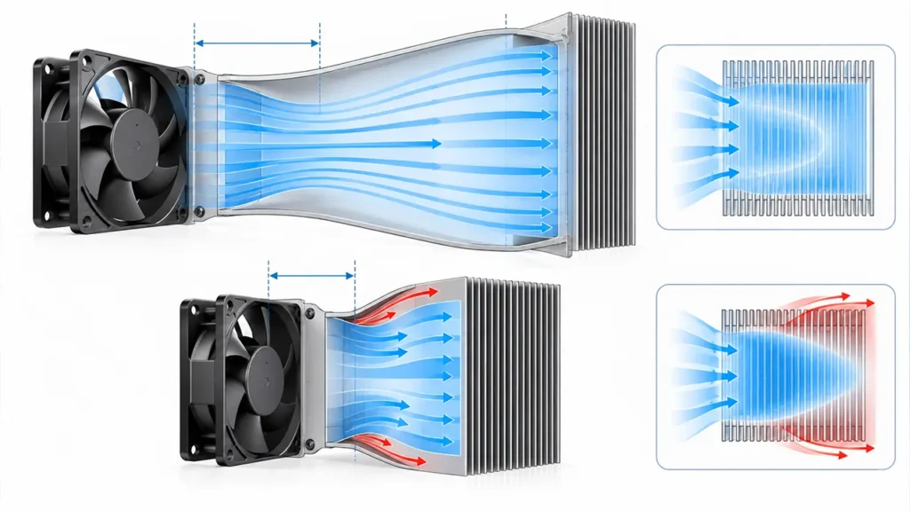
A well-designed cooling fan shroud turns the fan and the cooled component into one air system. It limits bypass, spreads flow across the useful area, and gives the air enough room to enter and leave the fan without severe separation. A poor shroud can do the opposite: it can cover part of the fan, create a sharp pressure loss, amplify turbulence, and leave a hot zone behind the motor hub.
What Is a Cooling Fan Shroud?
A cooling fan shroud is a structure that guides air between a fan and the component, heat sink, coil, radiator, filter, or enclosure opening it serves. It may be a molded plastic part, formed sheet metal, a gasketed panel, or part of the equipment housing.
For compact AC, DC and EC axial fans, the square or round fan frame already controls the blade-tip region. The equipment shroud normally surrounds that complete fan assembly and connects it to the cooling target. It should not be designed as an improvised close-fitting ring around the rotating blades unless the fan itself was engineered for that geometry.
A shroud is also different from a guard and a plenum. A guard prevents contact with moving parts. A plenum provides volume for pressure and flow distribution. A shroud guides and seals the flow path. One component can perform more than one function, but treating all three as the same part often leads to poor airflow.
What a Good Fan Shroud Needs to Do
The design has four practical jobs: keep air from bypassing the target, use as much of the target surface as possible, avoid unnecessary resistance, and remain safe under vibration, temperature and service conditions.
Block Bypass Air
Air follows the path with lower resistance. If there is an open gap around the edge of a radiator or heat sink, some flow will go around it instead of through its fins. The fan may still move a substantial volume of air, but the useful flow through the thermal core is lower.
Use a continuous panel, gasket, foam seal, or closely controlled joint where bypass matters. Pay particular attention to cable openings, corners, service gaps and the boundary between the shroud and heat exchanger. A small visible opening can matter when the intended path has a dense filter or high-fin-density core.
Cover the Cooling Target
A fan mounted directly against a larger heat exchanger tends to load the area under the blade annulus more strongly than the corners and the region behind the hub. Moving the fan away and using a distributing volume can improve coverage, but the added depth also consumes space and can introduce new leakage paths.
The goal is not to make velocity identical at every point. The goal is to keep all critical parts within temperature limits without adding unnecessary fan power or noise. If one component creates most of the heat, perfectly uniform airflow may be less useful than deliberately directing more air through that zone.
Avoid Creating a New Restriction
A shroud that narrows suddenly, covers the fan opening, or forces an immediate turn can add pressure loss. Compact axial fans are especially sensitive when the inlet is obstructed or the outlet discharges directly against a wall.
Use smooth changes in area where space allows. Keep screw bosses, ribs, wiring and structural brackets out of the main fan opening. If a transition must be short, prototype it instead of assuming that a steeper shape will behave like a longer diffuser or nozzle.
Maintain Mechanical and Service Clearance
The shroud must not touch the impeller or transmit harmful vibration into the fan frame. Allow for assembly tolerance, thermal expansion, fan replacement, cable routing and the movement of nearby panels. The best aerodynamic shape is not useful if a technician must bend it to remove the fan or if a gasket can be pulled into the inlet.
Tip: Before changing fan size or speed, temporarily seal obvious bypass gaps and repeat the temperature test. A large improvement indicates that airflow routing—not nominal fan capacity—is the first problem to solve.
Fan Shroud Coverage and the Hub Dead Zone
An axial fan does not discharge uniform velocity across its full square frame. The motor hub blocks the center, the blades create a rotating wake, and the support struts disturb the outlet flow. When the fan is pressed directly against a heat sink or filter, these features can appear as uneven cooling.
A spacing volume between the fan and target gives the flow some room to redistribute. This does not mean that more distance is always better. Greater spacing increases equipment depth, can allow recirculation, and may weaken local velocity where a concentrated jet is needed. The correct depth depends on fan size, target area, resistance, geometry and the temperature distribution that the equipment can accept.
If a large core is served by several fans, internal partitions may be needed. Without them, a running fan can move air backward through an idle or failed fan opening. Partitions can reduce that crossflow, but they also divide the plenum and may worsen coverage if they are placed without considering the heat load.
Clearance Around a Framed Axial Fan
Two clearances are often confused in shroud discussions.
Blade-tip clearance is the gap between a rotating blade tip and its surrounding fan casing. In a compact framed cooling fan, this geometry belongs to the fan design and should not be changed by the equipment builder. Research on axial fans shows that tip clearance and shroud geometry can affect leakage flow, efficiency and noise, but the optimum depends on the particular fan geometry rather than a universal percentage. One example is this study of tip clearance and shroud height in an axial fan.
Equipment clearance is the space between the complete fan and nearby panels, grilles, filters or thermal components. This is the dimension most equipment designers control. Too little inlet space can create nonuniform inflow and tonal noise. Too little outlet space can make the air turn abruptly and raise system resistance.
Do not transfer a tip-clearance value from a large automotive or HVAC fan to a compact LINKWELL framed fan. For equipment layout, begin with the selected fan drawing and its installation requirements, then validate the actual assembly.
Push, Pull and Shroud Position
A fan can push air into a heat exchanger, pull air through it, or be used with fans on both sides. The shroud requirements change with the arrangement.
Push Configuration
With the fan upstream, the shroud directs the discharge toward the target. This can deliver strong local velocity but may also reproduce the hub and blade-wake pattern on a nearby core. A distributing space can improve coverage. The inlet side still needs clear access to air; a well-shaped outlet cannot compensate for a blocked inlet.
Pull Configuration
With the fan downstream, the upstream shroud or plenum can draw air through a larger portion of the core. This arrangement may make the inlet to the fan turbulent if the fan sits too close to the fins or if the shroud contracts abruptly. Noise and operating stability therefore need to be checked, not assumed.
Push-Pull Configuration
Fans on both sides can provide more pressure capability, but they also add cost, power, wiring, noise and failure modes. The two fan curves, speed controls and spacing need to work together. Push-pull should solve a measured pressure or redundancy requirement, not simply compensate for an air path that leaks around the heat exchanger.
Axial Fan and Centrifugal Blower Shrouds Are Different
An axial fan moves air generally parallel to its shaft. Its equipment shroud usually connects two facing openings and manages coverage, spacing and sealing. A centrifugal blower takes air into an inlet and turns it toward a side outlet. Its housing is part of how pressure is developed and directed.
Trying to convert a compact axial fan into a side-discharge blower with a tight homemade cover usually creates severe restriction. If the air must make a tight 90-degree turn or pass through a narrow duct, a centrifugal blower may be the better starting point. Compare the required operating point and available space before designing a complex shroud around the wrong fan type.
How to Design a Cooling Fan Shroud
1. Define the Thermal Target
List the components that set the temperature limit, their heat load, the maximum allowable temperature, and the expected ambient condition. A shroud for a broad heat exchanger has a different job from a duct aimed at one power module.
2. Map the Intended Air Path
Mark where air enters, which restrictions it crosses, which surfaces must receive flow, and where heated air leaves. Include doors, cable bundles, filters, finger guards, louvers and unused openings. The drawing should make bypass and recirculation paths visible before tooling begins.
3. Select the Fan at the System Operating Point
Estimate or measure the pressure drop of the complete path. Choose the fan from its pressure-flow curve rather than its maximum free-air number. A shroud can improve how available airflow is used, but it cannot create pressure capability the fan does not have.
4. Establish Coverage and Spacing
Place the fan so that the shroud can reach the required area without blocking the inlet or forcing an abrupt outlet turn. Check the hub shadow, corners and any high-heat zone. For multiple fans, decide whether they share one plenum or need partitions.
5. Seal the Intended Path
Add sealing surfaces that are manufacturable and serviceable. A compressible gasket may work better than demanding a perfectly flat sheet-metal joint. Prevent loose foam, labels and cables from entering the fan.
6. Protect the Fan Without Choking It
Use guards and filters only where required, and evaluate their open area and pressure drop. A guard that looks visually open can still disturb the inlet when it is placed close to the blades. The article Fan Guard Airflow Restriction explains the interaction between guard geometry, pressure drop and noise.
7. Build a Prototype That Represents Production
A cardboard mock-up can reveal gross bypass, but it may not represent the leakage, stiffness and surface shape of a molded or sheet-metal part. Use early mock-ups for direction, then repeat the test with production-intent materials, fasteners, gaskets and clearances.
How to Validate the Shroud in the Finished Equipment
Do not approve a shroud from a single air-velocity reading. The final question is whether it keeps the equipment within its thermal limits across the expected environment and operating states.
- Measure ambient temperature and the temperature of each critical component.
- Record fan voltage, control command and speed feedback where available.
- Check pressure or airflow using a repeatable method appropriate to the assembly.
- Compare temperatures with and without temporary sealing of suspected bypass gaps.
- Use smoke, tufts, or another safe visualization method to find recirculation and stagnant regions.
- Repeat the test with the actual guard, filter, door and cable arrangement.
- Test a dirty-filter or reduced-airflow condition when it represents real service.
- Check noise and vibration after the thermal result is acceptable.
Thermocouples or other temperature sensors should be placed consistently and allowed to reach a defined steady condition. A thermal camera can locate hot regions, but surface emissivity and reflections can distort the displayed temperature. Use it to guide investigation, then confirm critical temperatures with an appropriate contact or calibrated method.
When the fan performs well on the bench but poorly in the assembly, review fan system effect and fan inlet clearance before selecting a higher-speed model.
Common Cooling Fan Shroud Problems
| Observed problem | Likely shroud or air-path cause | What to check |
|---|---|---|
| Hot corners on a large core | Fan is too close or the plenum does not distribute flow | Spacing, coverage and corner velocity |
| Center of the target remains hot | Motor hub shadow or a blocked central path | Fan-to-target spacing and heat-source position |
| Good fan speed but weak cooling | Bypass around the target or recirculation to the inlet | Edge seals, cable openings and inlet/outlet separation |
| Whine after the shroud is installed | Inlet turbulence, close grille, sharp edge or structural resonance | Inlet clearance, obstruction pattern and panel stiffness |
| Airflow falls after adding a filter | Higher system resistance moved the operating point | Filter pressure drop and fan curve |
| One fan drives air backward through another | Shared plenum without isolation during fan failure | Partitions, backflow path and redundancy strategy |
When CFD Helps—and When a Prototype Is Enough
CFD can be valuable when the enclosure has several fans, dense components, irregular passages, or expensive tooling. It can compare design directions and reveal recirculation or uneven core loading that is difficult to measure everywhere.
Its value depends on the inputs. An unrealistic fan boundary, missing leakage gap, simplified filter, or incorrect heat load can produce a clean image with the wrong conclusion. Use measured fan curves and realistic resistance data, then correlate the model with a physical prototype.
For a simple fan-to-heat-sink duct, careful mock-ups and temperature testing may answer the design question faster. The complexity of the analysis should match the cost of a wrong decision.
Information to Share with a Cooling Fan Supplier
Useful fan selection begins with the complete air path. Share the enclosure or shroud drawing, available fan size and depth, inlet and outlet clearance, filter or heat exchanger pressure drop, heat load, target temperatures, ambient range, altitude, power supply, control method, noise limit and expected duty cycle.
LINKWELL can use that information to compare suitable AC, DC or EC fan options and identify which operating-point and prototype checks should be completed. The shroud itself should still be validated in the finished equipment because the same fan can behave differently when the surrounding geometry changes.
Frequently Asked Questions
Does a cooling fan always need a shroud?
No. A compact fan mounted directly in a well-defined enclosure opening may not need a separate shroud. A shroud becomes useful when air must be sealed, redirected, distributed over a larger area, or prevented from bypassing the target.
How close should a fan be to a radiator or heat sink?
There is no universal distance. The correct spacing depends on fan size, hub diameter, target area, resistance, arrangement and acceptable temperature distribution. Prototype testing should confirm the final geometry.
Should the shroud cover the entire heat exchanger?
It should guide air through the useful heat-transfer area and block significant bypass paths. Full geometric coverage may not be necessary when heat load is concentrated, but uncovered areas should be a deliberate decision supported by testing.
Can a shroud increase fan airflow?
A shroud can increase useful airflow through the intended component by reducing bypass and improving distribution. It can also reduce total airflow if it introduces excessive resistance. Measure the installed result rather than assuming that any duct or cover is beneficial.
Is a smaller blade-tip gap always better?
Not as a universal equipment rule. Blade-tip clearance is part of the fan design and involves aerodynamic, mechanical, thermal and manufacturing considerations. Equipment designers using framed cooling fans should not alter that internal geometry.
Is a pull configuration better than a push configuration?
Not in every system. Pull can help distribute flow through a broad core, while push may provide stronger local delivery and easier access in some layouts. Inlet conditions, shroud geometry, pressure drop, noise, maintenance and measured component temperatures should decide.

