
A cooling fan in a cabinet or refrigeration unit may pulse, change pitch or deliver less airflow even though it is still rotating. It is tempting to call every unstable sound fan surge. In compact AC, DC and EC cooling systems, that diagnosis is often wrong.
A clogged filter, crowded inlet, unstable speed command, weak power supply or recirculating outlet air is usually more likely than full system surge. Fan stall and surge are real aerodynamic conditions, but you should separate them from control hunting and installation problems before changing the fan.
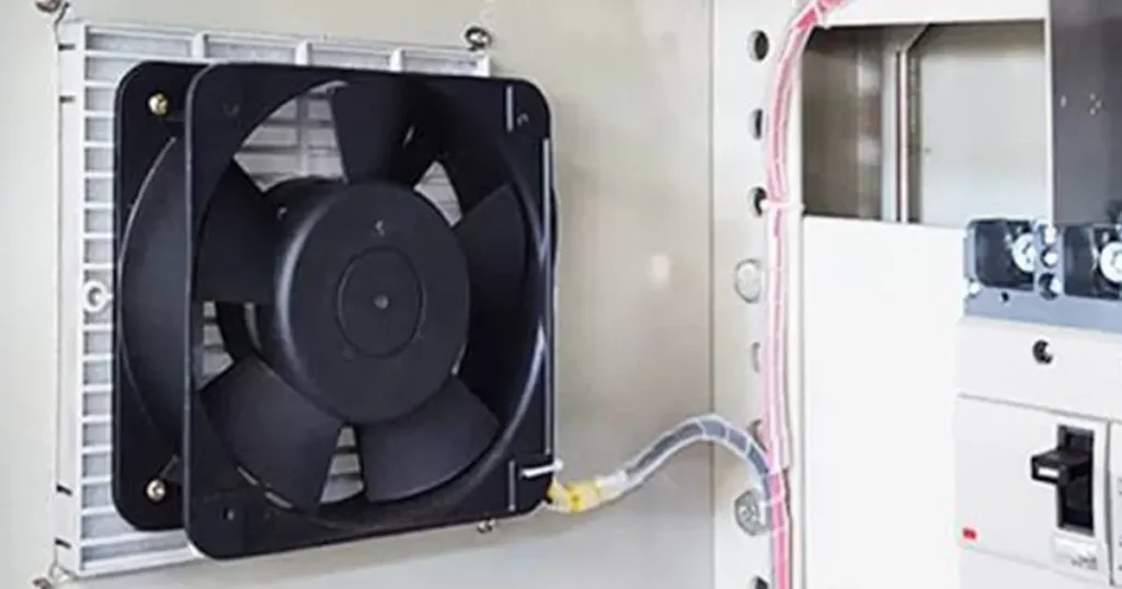
Fan stall vs surge: the practical difference
| Condition | What is happening | What you may notice |
|---|---|---|
| Fan stall | Air separates from part of a blade or blade passage because the incoming flow and blade loading are unfavorable | Rough aerodynamic noise, vibration, lower pressure or unstable airflow near a restricted operating point |
| Fan surge | The fan and connected air system cannot settle at one operating point, so flow and pressure oscillate together | Repeated pressure and airflow pulsation; severe cases can include temporary flow reversal |
| Control hunting | A temperature, pressure or speed-control loop repeatedly increases and decreases the command | Fan RPM rises and falls in step with PWM, 0-10 V or controller output |
| Mechanical or electrical fault | The fan is rubbing, loose, damaged or receiving unstable power | Noise or vibration may follow rotational speed without a corresponding pressure oscillation |
Stall begins at the blade or blade passage. Surge belongs to the fan-plus-system combination. One can contribute to the other, but they are not interchangeable terms.
Note: Do not diagnose surge from sound alone. First check whether fan speed, control command, pressure and equipment temperature oscillate together.
Why compact cooling systems need a different diagnostic approach
LINKWELL cooling fans are used in equipment such as electrical cabinets, refrigeration units, automation systems and electronic enclosures. These installations usually have short air paths and relatively small internal air volumes. They also contain filters, grilles, circuit boards, heat exchangers and cable bundles close to the fan.
As a result, a small installation change can have a large effect. Moving a cabinet wall closer to the inlet, adding a denser filter or fitting a finger guard can shift the operating point. An EC or DC fan controller can create a repeated speed change that sounds like an aerodynamic problem even when the fan curve itself is stable.
True system surge is possible when the fan characteristic and connected air volume create an unstable operating point. In compact cooling equipment, however, check the more common installation, control and power causes first.
What causes aerodynamic stall in a compact axial fan?
An axial fan blade needs air to approach at a suitable direction and velocity. If airflow is reduced too far or arrives with strong swirl and distortion, the air can separate from part of the blade surface. That region no longer produces pressure efficiently.
Conditions that can move a compact fan toward stall include:
- A filter or heat exchanger with more resistance than expected.
- A cabinet panel, cable bundle or component too close to the inlet.
- A grille or louver that blocks part of the fan face.
- Hot discharge air recirculating into the inlet.
- Several fans sharing an enclosure opening unevenly.
- A speed setting that places the fan in an unfavorable low-flow region.
Stall does not require every blade passage to separate at the same time. A localized stalled region can move around the fan annulus, creating pressure disturbances and tonal changes that a slow airflow measurement may not capture.
When can surge occur?
Surge requires interaction between the fan characteristic and the connected system. If a small change in airflow cannot produce a stable restoring pressure, the operating point may move back and forth rather than settle. The air volume in an enclosure, heat exchanger or connected plenum can store and release pressure during the cycle.
For compact equipment, surge risk increases when the fan is forced into a very low-flow region and the system contains enough air volume or compliance to sustain the oscillation. A highly restrictive heat exchanger, nearly blocked filter or poorly staged parallel fan arrangement can contribute.
A periodic breathing sound is only a clue. If rotational speed is changing at the same time, control hunting or supply instability may be the main cause. If speed is steady but pressure and airflow pulse, aerodynamic instability becomes more likely.
The five checks to make before calling it surge
1. Check for mechanical contact and damage
Disconnect and secure power according to the equipment procedure before touching the fan. Look for a loose guard, foreign object, damaged blade, cracked housing or cable touching the impeller. Confirm that mounting screws are secure and the frame is not twisted.
Mechanical contact often creates a repeating sound tied closely to RPM. It does not normally create the coordinated system-pressure cycle expected during surge.
2. Measure the supply at the fan terminals
A power supply can show the correct voltage with no load and still drop during fan startup or acceleration. Measure at the fan terminals while the symptom occurs. Check polarity for DC models and the applicable voltage and frequency for AC or EC models.
If several fans share one supply, record what happens when they start together. Repeated voltage drop and recovery can cause speed cycling without any aerodynamic surge.
3. Compare command and RPM
For a controlled DC or EC fan, record PWM duty, 0-10 V input or the relevant digital command together with tachometer or FG feedback. If the command rises and falls before the fan speed changes, investigate the controller, sensor location and control-loop settings.
A temperature sensor placed directly in a changing exhaust stream can make the controller overreact. An incorrect minimum speed, excessive gain or short delay can also produce hunting. The EC fan speed control guide explains how to separate power, command and feedback checks.
4. Inspect the complete air path
Check the filter, finger guard, louver, heat exchanger, inlet clearance and discharge opening. Look for only part of the fan face being blocked. Confirm that the fan direction matches the intended airflow and that hot outlet air cannot return directly to the inlet.
If the symptom began after a panel, filter or guard was changed, restore the previous safe configuration for comparison where practical. Do not permanently remove a required safety guard or environmental filter.
5. Locate the operating point
Use the fan curve and estimated system resistance to determine where the fan is operating. Maximum airflow is a free-air endpoint, not the installed result. A dirty filter or restricted opening moves the operating point toward lower airflow and higher pressure.
Read the full fan curve and compare it with the system resistance. If the supplier identifies a non-recommended or unstable region, keep the production duty away from it.
How to tell control hunting from aerodynamic instability
| Observation | More likely explanation | Next check |
|---|---|---|
| Command, RPM and sound rise and fall together | Control-loop hunting | Sensor position, controller gain, delay, minimum command and signal noise |
| Terminal voltage drops before RPM falls | Power-supply or wiring problem | Supply capacity, connector resistance, cable size and simultaneous fan startup |
| RPM remains steady while pressure pulses | Aerodynamic or system instability | Operating point, restriction, inlet distortion and connected air volume |
| Noise occurs once per revolution | Mechanical contact, damage or imbalance | Blade clearance, guard, mounting and impeller condition |
| Problem appears only as the filter loads | Rising system resistance | End-of-service filter pressure drop and fan pressure margin |
| One parallel fan behaves differently | Unequal branch resistance, backflow or control mismatch | Individual RPM, current, airflow path and failed-fan behavior |
When the equipment permits a safe test, hold the speed command at a documented fixed value. If the pulsing disappears, the control loop deserves attention. If RPM stays fixed while pressure continues to oscillate, investigate the aerodynamic operating point and system geometry.
Filters, grilles and inlet clearance are common root causes
A compact fan can lose a large share of its usable airflow when the inlet is crowded. A wall or cable bundle close to the fan does more than add resistance; it can feed one part of the impeller more strongly than another. That uneven approach flow increases noise and can encourage local separation.
Filters create a resistance range rather than one fixed number. The clean-filter condition may be acceptable while the loaded condition moves the fan too far left on its curve. Selection should therefore use the expected end-of-service pressure drop, not only the new-filter value.
The fan inlet clearance guide explains how nearby structures affect airflow. After correcting the layout, repeat the test with all production panels and accessories installed.
Parallel compact fans can imitate surge
When compact fans operate in parallel, they share a common pressure but do not automatically share airflow equally. Differences in branch resistance, fan speed or control command can make one fan carry more of the load. An inactive fan can also provide a backflow path.
Repeated staging between one and two fans may sound like surge if the controller switches too close to one threshold. Add suitable hysteresis and delay, then verify each operating combination. If redundancy is required, test temperatures and airflow with one fan unavailable rather than assuming the remaining fan reproduces the combined curve.
The article on fans in parallel vs series explains how the combined performance curve changes.
A practical correction order
| Finding | Correction to evaluate | How to confirm it worked |
|---|---|---|
| Blocked or distorted inlet | Increase clearance or reposition the obstruction | Recheck airflow, noise and critical component temperatures |
| Filter resistance too high | Use the correct maintenance condition or select more pressure capability | Test at clean and expected loaded-filter conditions |
| Control command hunts | Correct sensor placement and tune gain, delay, filtering and minimum speed | Record command and RPM during heat-load changes |
| Supply voltage cycles | Correct supply capacity, cable or connector losses | Measure stable terminal voltage through startup and full speed |
| Fan operates in an unstable curve region | Select a better matched fan or revise the airflow path | Plot the new operating point and repeat the equipment test |
| Parallel fans interact | Review staging, branch resistance, feedback and backflow protection | Test every normal and one-fan-out condition |
Do not treat reducing speed as a universal cure. Lower speed changes the fan curve, but the system may still operate in an unfavorable region. The correction must deliver stable airflow while keeping the cooled components within their temperature limits.
How to select a fan with enough stability margin
Provide the supplier with the required airflow, estimated pressure range, mounting space, voltage, control method, inlet temperature and altitude. Include the filter or heat-exchanger pressure drop and drawings of the fan inlet and outlet.
Ask for the complete airflow-pressure curve at the speed you plan to use. Check electrical input and noise at the intended operating point, not only the catalog endpoints. Allow margin for filter loading, production variation and environmental conditions without oversizing the fan so far that it must operate at very low flow.
For a LINKWELL selection, identify whether the fan will run at fixed speed, follow a temperature or pressure command, or operate with other fans. That information is necessary to evaluate the fan and the control strategy as one cooling system.
Frequently asked questions
Is fan stall the same as motor stall?
No. Aerodynamic stall is flow separation around a blade or blade passage. Motor stall means the rotor cannot continue rotating under the applied electrical and mechanical conditions.
Is a pulsing EC fan always surging?
No. Check the speed command, FG feedback and terminal voltage first. A control loop or power supply can make RPM cycle even when the aerodynamic operating point is stable.
Can a compact axial fan surge?
It is possible when the fan characteristic and connected air system form an unstable operating point. It is less common than restriction, recirculation, control hunting or electrical problems in many compact cooling applications.
Can a dirty filter cause fan stall?
A dirty filter raises system resistance and reduces airflow. This can move the fan toward a low-flow region where blade separation and unstable operation are more likely.
Does increasing fan speed solve stall or surge?
Not reliably. Increasing speed changes the available pressure and airflow, but it does not correct a blocked inlet, unstable controller, poor fan-system match or uneven parallel-fan loading.

