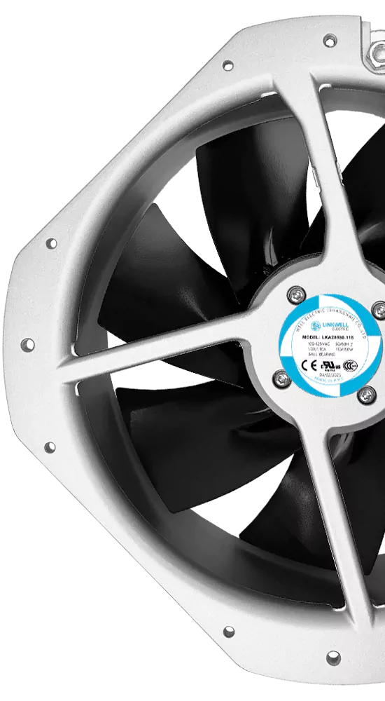
A fan that keeps a power module cool on the bench may still be the wrong choice for medical equipment. In the finished device, the same fan can produce an audible tone near a patient, disturb a sensitive measurement, draw more startup current than the power rail can supply or create a failure mode that the device control system cannot detect.
Medical equipment cooling fan selection therefore starts with the device risk and thermal architecture, not with a preferred frame size. Airflow, pressure, sound, life, control signals, electromagnetic behavior, cleaning exposure and service strategy all have to work together.
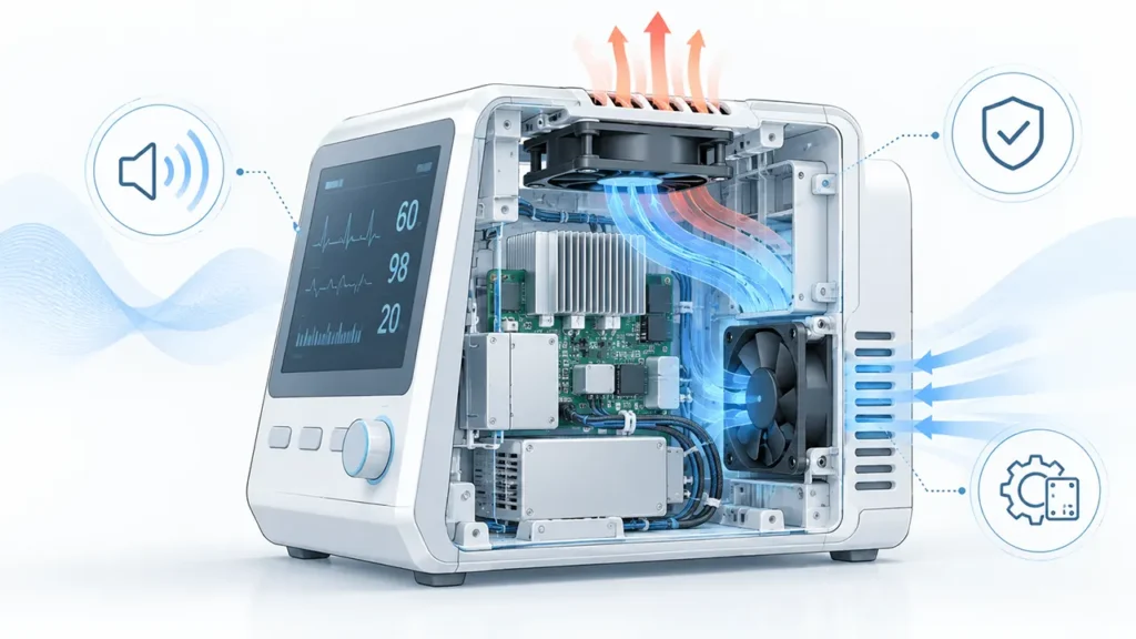
What Medical Equipment Is the Fan Cooling?
“Medical equipment” covers very different products: patient monitors, diagnostic analyzers, imaging subsystems, laboratory instruments, therapy equipment, power modules and mobile devices. A fan located in an operator console does not face the same acoustic, contamination or failure requirements as a fan near a patient or inside a high-power imaging cabinet.
Define the intended environment before selecting the fan. Is the device used beside a sleeping patient, in a laboratory, in a mobile cart or in a dedicated equipment room? Is the air path open to the room, filtered, isolated from the patient zone or contained in a heat exchanger? Will the fan be exposed to disinfectant vapor, lint, dust or periodic cleaning?
The answer determines which requirements are critical. A low sound level may dominate a bedside device. Pressure capability and redundancy may dominate a high-heat subsystem. A small portable instrument may be limited by battery power, startup current and the depth available behind the grille.
Start with the Device-Level Thermal Requirement
List the heat released by processors, displays, power supplies, light sources, motors, detectors and charging circuits at the worst operating mode. Include simultaneous functions, battery charging and a fault or degraded state when the risk analysis requires it. Use measured or manufacturer-provided loss data rather than assuming that all input power becomes heat in the same compartment.
Define maximum ambient temperature, altitude, allowed component temperatures and the temperature of air entering the fan. The fan may sit downstream of a hot power supply, so room temperature alone is not enough.
A first ventilation estimate can use:
Airflow (m3/h) = 3.0 x heat load (W) / allowable air temperature rise (C)
This ideal estimate does not include filters, guards, acoustic foam, heat sinks, internal partitions or flow recirculation. It must be converted into an operating point on the pressure-airflow curve and verified in the complete device.
Airflow and Static Pressure Matter Together
Compact medical equipment often has narrow vents, EMI screens, finger guards, filters and densely packed circuit boards. These features create system resistance. A fan rated for high free-air airflow can lose much of its delivery after installation.
Estimate or measure the pressure drop through the intended air path, then compare the exact fan curve. The working point is where the fan curve meets the system curve. Check the worst-case condition, including a filter near its service limit and the lowest permitted fan speed.
Standardized fan testing, including the procedures described by ISO 5801, supports repeatable product data. It does not replace testing in the finished medical equipment, where inlet geometry, outlet geometry and system effect can change performance.
Use how to read a fan curve and the fan system effect guide when the measured device airflow falls below the curve expectation.
Design the Air Path Around the Heat Source
Provide a clear supply route to the critical components and a separate path for heated air to leave. Prevent exhaust from returning to the inlet, and seal bypass gaps that allow cool air to miss the heat sink or power module. A high total airflow number is not useful if most of the air travels around the component.
Consider the user’s environment. Exhaust should not create an uncomfortable draft or direct warm air, dust or odor toward a patient or operator. If the device handles samples, sterile fields or controlled air, the system designer must assess whether forced airflow is acceptable at all.
Keep cables, foam, labels and service parts away from the impeller. A production device may be assembled differently from the engineering prototype, so airflow clearances should be controlled by the mechanical design rather than by informal cable routing.
How to Set the Acoustic Requirement
Do not select only from a single datasheet dBA number. First establish where sound matters: at the patient position, operator position or a standardized measurement point. Confirm whether the published value is sound pressure or sound power and under what distance, voltage and airflow condition it was measured.
Aerodynamic sound increases when the fan works against a restrictive grille or receives disturbed inlet flow. Motor commutation and bearings can add tones that are more noticeable than broadband airflow noise. The device panel can amplify vibration even when the standalone fan sounds acceptable.
Variable-speed control can keep the fan quiet during light load, but the control profile must preserve thermal margin. Avoid rapid speed hunting around a temperature threshold. A gradual control response with defined minimum speed and hysteresis is often easier to listen to and easier to validate.
Measure tonal content, vibration and transient behavior as well as overall dBA. Confirm that cooling noise does not interfere with intended audible signals, speech or the clinical use environment. The article on axial fan noise reduction covers clearance, restriction and vibration controls.
Tip: Compare fan candidates in the real housing at the same thermal duty, not at the same PWM duty cycle. Equal control commands do not guarantee equal airflow, temperature or sound.
Reliability Is More Than a Life-Hours Number
Fan life depends on the exact bearing system, temperature, speed, orientation, contamination and duty cycle. A published life value is meaningful only with its definition and test condition. L10 life, expected life and MTBF describe different things and should not be substituted for one another.
Place the fan so it receives the coolest practical air. Bearing temperature can be higher than room temperature when the fan sits behind a hot power module. Confirm the permitted mounting orientation and evaluate transport shock, vibration and repeated on-off cycling.
If loss of airflow can cause a hazardous situation or loss of essential performance, the response belongs in the device risk management process. Options may include temperature sensing, FG speed feedback, an RD alarm, a redundant fan, power derating or a controlled shutdown. The right response depends on the device; installing two fans does not automatically create fault-tolerant cooling.
Review fan L10 life versus MTBF, FG tachometer feedback and fan redundancy before defining the monitoring strategy.
Electrical Integration: Voltage, Startup and Control
Match the fan to the actual supply at its connector, including tolerance, cable drop and transient behavior. A 12 V or 24 V label is not a complete operating specification. Check the approved voltage range and minimum reliable starting condition for the exact model.
Startup current can exceed steady-state current or interact with current limiting in the medical equipment power supply. Test simultaneous fan starts, battery operation and low-line conditions. A fan that repeatedly attempts to start can create temperature, acoustic or power-rail disturbances that are not visible in a simple running-current check.
For PWM control, confirm signal voltage, frequency, duty-cycle range, input circuit and behavior at zero command. For FG or RD outputs, confirm pull-up requirements, pulses per revolution, alarm logic and the controller’s fault thresholds. Model options vary; do not infer the wire functions from color alone.
EMC, Safety and Medical Device Compliance
IEC 60601-1 addresses general requirements for the basic safety and essential performance of medical electrical equipment. IEC 60601-1-2 addresses electromagnetic disturbances and related tests for medical electrical equipment and systems. The applicable edition, national adoption and any particular standard depend on the target device and market.
A cooling fan is only one component in that assessment. Selecting a fan described as low-noise, protected or compliant with a component requirement does not make the finished medical equipment compliant. The device manufacturer must verify creepage, insulation, grounding, leakage, mechanical protection, EMC, temperatures, abnormal operation and other applicable requirements at the system level.
Motor commutation, PWM wiring and cable routing can contribute conducted or radiated emissions. Keep power and feedback wiring appropriately routed, apply the required grounding and filtering strategy, and test the installed device. Do not add suppression parts or change PWM conditions without checking fan operation and the medical equipment design file.
ISO 14971:2019 defines a risk-management process for medical devices. Fan failure, blocked airflow, excessive temperature, unexpected noise and loss of monitoring should be evaluated as device-level hazards or contributing events where relevant.
Cleanliness, Filters and Cleaning Exposure
A filter can reduce dust entering an open-loop device, but it also adds pressure drop and creates a maintenance requirement. Define the acceptable loaded condition and make the filter accessible without exposing users to a moving impeller or live parts. If the device has no planned filter service, verify that long-term contamination will not reduce cooling below the required margin.
Disinfectant and cleaning agents can affect plastics, labels, adhesives, seals and bearing protection. Exposure depends on where the fan is mounted and how the device is cleaned. Confirm material compatibility for the specific agent and concentration rather than describing a standard fan as universally chemical-resistant.
Airflow can transport particles and aerosols. Equipment used near a sterile field, biological sample or controlled patient airflow needs a device-specific contamination assessment. A sealed heat exchanger or isolated air circuit may be more appropriate than drawing room air across internal electronics.
Mechanical Integration and Serviceability
Check frame size, depth, mass, mounting-hole pattern, guard, screw engagement, connector position and cable bend radius. Keep adequate inlet and outlet clearance. Avoid uneven screw torque that distorts the frame or transfers vibration into a lightweight housing.
Confirm the bearing system and approved mounting orientation. A fan installed flat in a cart or overhead module may have different bearing and panel-vibration conditions from a vertical bench test. The cooling fan mounting orientation guide explains what to verify.
Plan how the fan will be inspected and replaced. If replacement is expected during the device service life, use a controlled connector and routing method that prevents reverse polarity, wrong fan direction or contact with the impeller. After replacement, the service procedure should verify airflow direction, alarm function and device temperature.
AC, DC or EC Fan for Medical Equipment?
| Fan type | Potential fit | Questions to resolve |
|---|---|---|
| DC axial fan | Compact equipment with low-voltage power, PWM and speed feedback | Voltage range, startup current, control mapping, FG or RD |
| EC fan | Systems needing efficient variable speed or a wider power architecture | Input and control interface, EMC, minimum speed and fault behavior |
| AC axial fan | Fixed installations with suitable AC power and simple operation | Frequency, insulation system, noise, control and monitoring needs |
| Centrifugal fan or blower | High-resistance air paths, ducts or compact heat exchangers | Curve at pressure, outlet geometry, sound and vibration |
Choose by the operating point and integration requirement, not by motor category alone. A compact axial fan is effective when the pressure demand is moderate and the air path is direct. A centrifugal fan may suit a more restrictive path, but it changes packaging, outlet direction and acoustic behavior.
Verification Tests Before Release
- Measure critical component temperatures at maximum load, maximum ambient and minimum permitted supply.
- Test the production-intent enclosure with guards, filters, foam, cables and covers installed.
- Verify startup, speed control and monitoring across the full voltage and temperature range.
- Evaluate a blocked or service-limit filter when the device risk analysis requires it.
- Inject relevant fan faults and confirm the alarm, derating or shutdown response.
- Measure sound and vibration at the intended patient and operator positions.
- Complete device-level EMC, electrical safety, cleaning and environmental validation.
- Document the approved fan model and assess any future substitution as a controlled change.
LINKWELL supplies AC, DC and EC cooling fan solutions with model-specific voltage, airflow, pressure, bearing, control and feedback options. For a selection review, provide the device air-path drawing, heat load, required operating point, ambient range, acoustic target, power rail, control signal, monitoring requirement, cleaning exposure and regulatory design constraints. Any compliance or lifetime statement should be tied to the exact model and documented condition.
Frequently Asked Questions
What type of fan is used in medical equipment?
DC axial fans are common in compact low-voltage equipment, while EC, AC and centrifugal options can suit other power and pressure needs. The correct type depends on the device operating point and integration requirements.
Does a medical equipment cooling fan need IEC 60601 certification?
IEC 60601 requirements apply to the medical electrical equipment and its applicable system-level evaluation. A fan component does not by itself establish compliance of the finished device.
How can fan noise be reduced near a patient?
Use a low-resistance air path, adequate fan size, controlled speed, good inlet clearance and vibration isolation. Compare candidates in the real housing at the same thermal duty.
Should a medical device use fan redundancy?
Only when the device risk analysis and cooling requirement justify it. Redundancy must be verified under an actual one-fan-failed condition, including possible reverse flow.
Can an FG signal prove that cooling is adequate?
No. It can confirm rotation when correctly interpreted, but it cannot detect every blocked filter, reversed installation, recirculation path or heat-transfer problem.
Can one fan model be substituted for another with the same size and voltage?
Not without review. Airflow-pressure performance, startup current, sound, bearing, control signals, materials and EMC behavior may differ even when the frame and voltage match.