
A controller shows a clean 50 percent PWM command, yet the fan runs at full speed, pulses, hums, refuses to start, or reports an unstable tachometer signal. The duty-cycle setting may be correct. The problem can be the signal frequency, electrical interface, wiring, or the fact that the controller is switching the fan’s power instead of driving a dedicated control input.
PWM fan frequency tells you how often the control waveform repeats each second. It matters because the fan electronics must recognize every cycle correctly. Frequency does not normally request the speed by itself; duty cycle carries that command. Both values must stay inside the limits specified for the exact fan and controller.
What Is PWM Fan Frequency?
PWM fan frequency is the number of complete control-signal cycles that occur each second. It is measured in hertz (Hz) or kilohertz (kHz). A frequency of 1 kHz means 1,000 cycles per second; 25 kHz means 25,000 cycles per second.
Frequency and period describe the same waveform from different directions:
Period = 1 / frequency
At 25 kHz, one complete period is 40 microseconds. Duty cycle then describes how much of that 40-microsecond period is in the active state. The fan input circuit observes the repeating waveform and interprets the duty cycle according to its own control design.
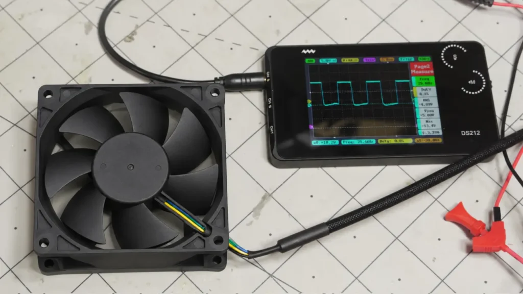
Measure frequency at the fan connector, referenced to the correct signal common. A microcontroller timer may be configured for the intended value while an isolator, level shifter, long cable, incorrect pull-up or overloaded output changes the waveform that actually reaches the fan.
Do not confuse three different frequencies:
- PWM control frequency is the repetition rate of the command signal.
- Motor commutation or internal switching frequency belongs to the fan’s drive electronics.
- FG or tachometer frequency depends on rotor speed and the number of output pulses per revolution.
These signals can all appear in the same cooling system, but they perform different jobs and normally have different values.
How Does PWM Control Fan Speed?
PWM changes a fan’s speed by presenting an on-and-off waveform with a controlled duty cycle. How that waveform reaches the motor depends on the fan interface.
Dedicated PWM input
A typical four-wire DC fan receives continuous power on its supply leads, provides an FG or tachometer output, and accepts a low-power PWM command on a separate control lead. The fan’s internal electronics read the command and control the motor. The external controller is not normally switching the full fan current through the PWM pin.
This arrangement keeps the fan electronics powered while speed changes, so feedback can remain available. However, the controller must still match the required frequency, active polarity, voltage thresholds, output topology and common reference.
PWM applied to the fan power
A two-wire fan, or a three-wire fan without a dedicated speed input, may be controlled by switching its supply through an external transistor. In that arrangement, the whole fan electronics repeatedly power up and down. The acceptable frequency, starting behavior, electrical noise and tachometer behavior can be very different from a four-wire control input.
Calling both methods “PWM fan control” can hide the most important design difference. Always identify which conductor is being switched before choosing a frequency. The broader PWM fan guide explains the basic control concept, while this article focuses on frequency and interface compatibility.
PWM input on an EC fan
An EC fan may also accept a PWM command, but its electrical interface is not automatically the same as a PC-style four-wire DC fan. The required amplitude, frequency, isolation, reference terminal, active state and duty-to-speed mapping must come from the exact EC fan specification.
PWM Frequency vs Duty Cycle
Frequency sets how often the waveform repeats. Duty cycle sets how much of each period is active. They should be checked separately.
| Parameter | What it describes | What it controls or affects |
|---|---|---|
| PWM frequency | Number of complete signal cycles per second | Whether the fan input can recognize the waveform and how the interface behaves |
| Period | Time occupied by one complete PWM cycle | Available active and inactive time within each cycle |
| Duty cycle | Percentage of each period in the defined active state | The requested speed or power level, according to the fan design |
| Fan speed | Actual rotor RPM | Result of duty cycle, fan control logic, supply, load and operating conditions |
The basic duty-cycle relationship is:
Duty cycle (%) = active time / period x 100
Two signals can both be 25 kHz while one has 30 percent duty cycle and the other has 80 percent duty cycle. Their periods are the same, but the active time is different. A compatible fan will normally interpret the second command as a higher speed request, subject to its minimum speed, maximum speed and control curve.
Changing frequency is not the normal way to request a different RPM. If a controller varies frequency instead of duty cycle, the fan may reject the command, misread it, or respond unpredictably unless the interface was specifically designed for frequency control.
Tip: When a fan runs at the wrong speed, record frequency and duty cycle as two separate measurements. A display showing “50% PWM” does not prove that the frequency is compatible.
Why Does PWM Frequency Matter?
Controller compatibility. The fan input circuit is designed to recognize a particular frequency range and electrical waveform. Outside that range, the edges may arrive too slowly, too quickly or with insufficient time for the input circuit to register the intended duty cycle.
Stable operation. A suitable frequency helps the fan convert the command into a steady speed. An incompatible signal can produce hunting, pulsing, a fixed fallback speed, failure to start, or no response at all. The exact symptom depends on the fan’s input filtering and firmware.
Acoustic behavior. Low-frequency power switching can create audible speed or torque modulation. A dedicated high-frequency control input may move command-related switching above the most sensitive audible range, but mechanical, aerodynamic and motor-commutation noise can still remain. High frequency is not a guarantee of a silent fan.
Speed response. The fan must average or decode the command while its own control loop accelerates and decelerates the rotor. Frequency that matches the input specification supports predictable control; actual response time still depends on fan inertia, internal ramp limits and the equipment controller.
Feedback quality. Chopping power to a three-wire fan can interrupt the electronics that generate the tachometer signal. A four-wire fan keeps its power applied and usually provides cleaner continuous feedback, but the tachometer output still needs the correct pull-up and measurement method.
Electrical behavior. Output-transistor switching loss, cable capacitance, edge quality and electromagnetic emissions can change with frequency. These effects are especially important when one controller drives several fans or when cables are long.
What Happens If PWM Frequency Is Too Low?
A PWM frequency below the approved range gives each active and inactive interval more time. The result depends heavily on whether the signal is a dedicated control input or the fan’s power supply.
On a dedicated PWM input
The fan may still respond, but speed can become less smooth or the input may fall outside the range that its internal filter and firmware expect. Possible symptoms include audible modulation, speed ripple, delayed response, minimum speed that is higher than expected, or repeated stopping and starting at low duty cycle. Some fans may ignore the signal and use a default speed.
When the fan power is being switched
The entire fan electronics turn off during each inactive interval. At a low frequency, the rotor can slow noticeably between pulses and the controller may repeatedly enter its startup sequence. This can create pulsing airflow, clicking or tonal noise, and unstable starting at low duty cycle.
For a three-wire fan, the tachometer circuit also loses power during the off interval. The feedback waveform can be chopped or stretched, so a controller may calculate the wrong RPM unless it uses a measurement method intended for power PWM.
A low frequency is not automatically unsafe, and some power-switched fan systems are designed around it. The mistake is applying a value chosen for one interface to another without checking the fan and controller documentation.
What Happens If PWM Frequency Is Too High?
A frequency above the approved range shortens every period. At the same duty cycle, the active and inactive pulses become narrower. If the fan input or controller cannot reproduce and recognize those pulses correctly, the effective duty cycle at the fan can differ from the commanded value.
Common causes include limited rise and fall time, an unsuitable pull-up resistor, cable capacitance, slow isolators, transistor storage time and input filtering inside the fan. The waveform may look correct at the microcontroller pin but become rounded or fail to reach valid logic thresholds at the fan connector.
When PWM switches the full fan supply, higher frequency also increases the number of power-switch transitions per second. That can raise switching loss in the external transistor, increase electromagnetic emissions and interact with the fan’s input capacitors or internal driver. A frequency that is convenient for the microcontroller timer may therefore be a poor choice for the power stage.
Too-high frequency does not have one universal failure mode. The fan may run at a fixed speed, show a compressed control range, fail to reach full command, become unstable, or appear to ignore PWM. Do not increase frequency until the symptom disappears without first confirming the permitted range and checking the waveform at the load.
Is There a Standard PWM Frequency for Cooling Fans?
There is no single PWM frequency that applies to every cooling fan. Different fan drivers, input filters, control interfaces and applications can require different values. The correct frequency is the range stated for the exact fan model and control option.
A commonly used four-wire interface illustrates why one frequency cannot be applied blindly. Some PC-style four-wire fans specify a high-frequency PWM range around 25 kHz. That convention is useful only when the selected fan is confirmed to use the same electrical interface, logic levels, polarity and timing.
That example should not be turned into a rule for every industrial fan. A LINKWELL DC fan, low-voltage EC fan, mains-powered EC fan or customized controller may specify a different frequency, logic level, polarity or speed curve. A fan that accepts PWM on a dedicated control lead can also have different requirements from a two-wire fan whose power is being switched.
Note: “Use 25 kHz” is complete advice only when the selected fan is confirmed to use the corresponding four-wire interface. For every other case, it is an assumption that still needs verification.
If the datasheet does not state a PWM frequency, request the electrical control specification before finalizing the controller. A sample that happens to respond at one bench setting does not establish a production limit across temperature, cable length and component tolerance.
PWM Control in 2-Wire, 3-Wire and 4-Wire Fans
The number of wires often indicates how speed control and feedback are arranged, but wire color and pin function are not universal. Use the approved wiring diagram for the exact model.
| Typical fan type | Usual conductors | How PWM may be applied | Main concern |
|---|---|---|---|
| 2-wire fan | Power and ground | External circuit switches fan power, if the model permits power PWM | Startup, pulsing current, acoustic noise and no dedicated speed feedback |
| 3-wire fan | Power, ground and FG or tachometer | Supply-voltage control or power PWM, depending on the fan and controller | Tachometer circuitry can be interrupted when power is switched |
| 4-wire fan | Power, ground, FG or tachometer and PWM input | Continuous fan power with a separate logic-level control signal | Frequency, duty cycle, voltage thresholds, polarity and output topology must match |
| EC fan with control terminals | Power plus PWM, analog or communication terminals | Dedicated input interpreted by integrated electronics | Do not assume the interface is electrically identical to a PC four-wire fan |
A four-wire arrangement is generally easier to monitor because the tachometer electronics remain powered while the PWM input changes speed. Even so, a low duty cycle may command stop or minimum speed depending on the fan, and an open control wire may cause full speed, minimum speed or another configured fallback.
The DC axial fan wiring guide covers typical 2-wire, 3-wire and 4-wire connections. Use it to understand the functions, then return to the exact model drawing before connecting power or a controller.
PWM Signal Requirements Beyond Frequency
Matching the number of kilohertz is only one part of PWM compatibility. The signal can have the correct frequency and still fail because the electrical interface is wrong.
| Signal item | What to confirm | Typical failure if mismatched |
|---|---|---|
| Input type | Dedicated PWM command, switched power, analog input or another interface | Controller drives the wrong terminal or wrong circuit |
| Voltage and logic thresholds | Permitted high level, maximum low level and absolute input limit | Fan never sees a valid high or low state |
| Output topology | Open-collector, open-drain, push-pull, isolated contact or another driver | Contention, wrong pull-up voltage or damaged interface |
| Active polarity | Whether high or low is the active part of the duty cycle | Speed command appears inverted |
| Frequency range | Minimum, nominal and maximum accepted frequency | No response, unstable response or reduced control range |
| Duty-cycle range | Valid command range and behavior below the minimum | Unexpected stop, minimum speed or failure to start |
| Reference or common | Required signal return and whether the input is isolated | Floating or noisy command |
| Rise and fall time | Edge-speed limits after cable and interface components | Effective duty-cycle error or missed pulses |
| Loss-of-signal behavior | Full speed, minimum speed, stop, hold-last-command or alarm | Unsafe fallback when a cable opens or controller resets |
Many four-wire interfaces expect the controller to pull the PWM line low and release it rather than actively drive both states. That is commonly implemented with an open-collector or open-drain output and a pull-up defined by the interface. Do not connect a generic industrial 24 V push-pull PWM output to a low-voltage fan input unless the specification explicitly allows it.
Controller ground and fan signal common must also be handled correctly unless the input is isolated. A perfect waveform measured against the controller ground can be invalid at the fan if ground offset, long wiring or high current in the return conductor changes the signal reference.
How to Select a PWM Cooling Fan
Select the fan and controller as an interface pair. Begin with the cooling duty, then confirm every electrical detail that allows the fan to reach it.
- Define the fan power. Record rated voltage, operating range, startup current, polarity and the number of fans that may start together.
- Identify the control method. Decide whether the system uses a dedicated PWM input, supply-voltage control, switched-power PWM, 0-10 V control or digital communication.
- Match the PWM specification. Confirm frequency range, duty-cycle range, logic thresholds, active polarity, output topology, pull-up and signal common.
- Define low-command behavior. Decide whether the fan should stop, hold a minimum speed or use another response below the minimum command.
- Define feedback. Confirm FG or tachometer output type, pulses per revolution, pull-up requirement and fault-detection timing.
- Check the air duty. Select from required airflow and static pressure in the real enclosure, not only maximum free-air CFM.
- Check mechanical and acoustic limits. Confirm frame size, thickness, mounting, inlet and outlet clearance, guard, filter and noise target.
- Validate the failure state. Test controller reset, open PWM wire, missing common, fan lock and lost tachometer feedback.
A duty-cycle command is not an airflow guarantee. The same percentage can produce different RPM on different fan models, and the same RPM can deliver different airflow after filters, heat sinks and enclosure resistance are added. Use the fan curve and installed temperature result to approve the setting.
For LINKWELL fan selection, provide the supply voltage, fan size, required airflow and pressure, PWM frequency and electrical interface, desired duty-to-speed behavior, FG or alarm requirement, connector, cable length and noise limit. Control options vary by model, so the final recommendation should be tied to an approved specification rather than a general “PWM fan” label.
How to Validate PWM Control in the Final Equipment
Validation should be performed at the fan terminals and in the final airflow path. A controller-register value is useful, but it does not show whether the waveform survived the wiring and interface circuit.
- Verify the power rail first. Measure fan-terminal voltage during startup and at full command. Make sure it remains inside the approved operating range.
- Measure PWM at the fan connector. Check frequency, duty cycle, high and low levels, polarity, rise and fall time, and the correct signal reference.
- Test several commands. Record actual RPM at minimum, intermediate and maximum duty cycle. Do not assume a linear duty-to-RPM relationship.
- Test from a stopped rotor. Power-cycle the system and command startup from the lowest intended setting. Repeat at cold and hot conditions relevant to the equipment.
- Apply command steps. Move between low and high settings and check for overshoot, hunting, delayed response and controller timeouts.
- Verify feedback. Compare FG or tachometer readings with an independent speed measurement where practical. The fan tachometer signal guide explains pull-ups and pulse interpretation.
- Test loss of control. Confirm the safe response to an open PWM conductor, controller reset, invalid frequency and missing common.
- Check the cooling result. Run the real heat load with production filters, guards and panels installed, then verify component temperatures and noise.
If several fans share one PWM output, calculate the combined input load and inspect the farthest connector. Cable capacitance and parallel pull-ups can slow the edges or overload the controller. Also check whether one failed input can hold the shared line in an incorrect state.
Starting behavior deserves its own test. A fan may follow PWM normally after it is spinning but fail to start at the minimum command. Compare the result with the system’s cooling fan startup current and any startup-boost logic.
Common PWM Fan Control Problems
| Symptom | Likely checks | Why frequency may not be the only cause |
|---|---|---|
| Fan does not start | Supply sag, minimum duty, enable state, startup boost, polarity and permitted frequency | The PWM signal can be valid while the power rail collapses |
| Fan always runs at full speed | Open control wire, wrong output topology, missing common, fallback setting or invalid logic levels | Many designs use full speed as a safe loss-of-signal response |
| Minimum speed is too high | Fan’s minimum command, duty calculation, inverted polarity and model speed curve | The fan may clamp low commands to a minimum RPM |
| Speed pulses or hunts | Frequency range, noisy edges, control-loop settings, power stability and fan operating point | Thermal or pressure control can hunt even with a clean PWM input |
| Speed command is inverted | Definition of active state and transistor logic | The displayed duty cycle may use the opposite polarity from the fan |
| Tachometer reading is wrong | Pull-up, pulses per revolution, measurement window and whether power is being chopped | Feedback has its own interface and frequency |
| Controller transistor becomes hot | Whether it switches fan current, gate drive, switching loss and total fan load | A dedicated PWM input requires far less current than power PWM |
| Several fans respond differently | Model revisions, shared-line loading, cable length, input thresholds and individual system resistance | Equal duty cycle does not guarantee equal RPM or airflow |
| Audible hum or clicking | Power-switching frequency, repeated startup, mechanical resonance and commutation noise | Raising frequency may hide one tone while leaving the actual fault unresolved |
Troubleshoot in a fixed order: confirm the exact interface, check fan power, measure PWM at the fan, verify the response curve, then inspect the installed airflow and thermal result. Changing frequency first can temporarily change the symptom without fixing the incompatibility.
Frequently Asked Questions
What is PWM fan frequency?
It is the number of complete PWM control cycles per second, measured in Hz or kHz. The value must fall within the input range specified for the fan and controller.
Does PWM frequency control fan speed?
Normally, no. Frequency sets how often the signal repeats, while duty cycle carries the speed request. The fan’s internal control curve then converts that request into an RPM. Changing frequency outside the specified range is not a valid speed-control method.
What is the difference between PWM frequency and duty cycle?
Frequency is cycles per second. Duty cycle is the percentage of each cycle spent in the defined active state. Two signals can have the same frequency but different duty cycles and therefore request different speeds.
Can the wrong PWM frequency damage a fan?
An incorrect frequency on a dedicated PWM input more often causes poor or unpredictable control than direct damage, provided the signal voltage and driver topology remain within specification. Damage becomes more plausible when excessive voltage is applied, outputs fight each other, or full fan power is switched through an unsuitable transistor at an excessive frequency. Lost cooling can also damage the equipment even when the fan input survives.
What frequency should I use for a PWM fan?
Use the nominal frequency and permitted range in the exact model datasheet. Some PC-style four-wire fans use a range around 25 kHz, but industrial DC and EC fan inputs can specify different values. Do not choose from the connector shape alone.
Do all 4-wire fans use the same PWM frequency?
No. Four wires usually indicate power, ground, feedback and control, but they do not guarantee one electrical interface. Confirm frequency, logic thresholds, polarity, output type, pull-up and loss-of-signal behavior.
Can a 2-wire fan use PWM control?
Some two-wire fans can be controlled by switching their power with an external transistor, but only when the fan and controller are designed for that method. Starting, acoustic noise, current pulses and the suitable frequency can differ greatly from a dedicated four-wire PWM input.
LINKWELL supplies DC and EC cooling fans with speed-control and feedback options that vary by model. Share the supply voltage, fan size, required airflow and static pressure, PWM frequency, duty-cycle range, signal voltage, output topology, FG or alarm requirement and cable details so the control interface can be checked before selection.

