
A round EC axial fan is not automatically more efficient, and a square EC axial fan is not automatically better for a cabinet. The frame shape mainly changes how the fan mounts, seals to the opening and connects to the surrounding airflow path. The motor, impeller, inlet geometry and operating point still determine most of the aerodynamic result.
This is why two fans with the same nominal diameter can behave very differently after installation. One may fit a circular heat exchanger neatly but leak around a rectangular panel opening. Another may bolt into a standard square cutout yet lose airflow because the grille and internal components crowd its inlet.
The short answer
Choose the frame that matches the opening and airflow path you are designing.
| If your priority is… | Usually start with… | Reason |
|---|---|---|
| A compact fan mounted directly to a flat equipment panel | Square frame | Four-corner mounting, predictable envelope and straightforward panel sealing |
| A circular duct, wall ring, condenser opening or heat-exchanger aperture | Round frame or round mounting plate | The frame follows the opening and can support a smoother inlet transition |
| A drop-in replacement | The existing frame geometry | Cutout, hole pattern, connector and airflow direction matter more than nominal diameter |
| Lowest energy or sound at the duty point | Whichever tested assembly performs better | Shape alone does not prove efficiency or acoustic performance |
EC describes the electronically commutated motor and integrated drive. It does not prescribe a round or square housing. Both formats can offer variable-speed control, feedback and high part-load efficiency when those functions are designed into the model.
Selection note: Treat the fan, inlet ring, guard, panel cutout and nearby heat exchanger as one aerodynamic assembly. Choosing the motor and frame in isolation misses the installation losses that often decide the result.
What ?round? and ?square? mean on an EC axial fan
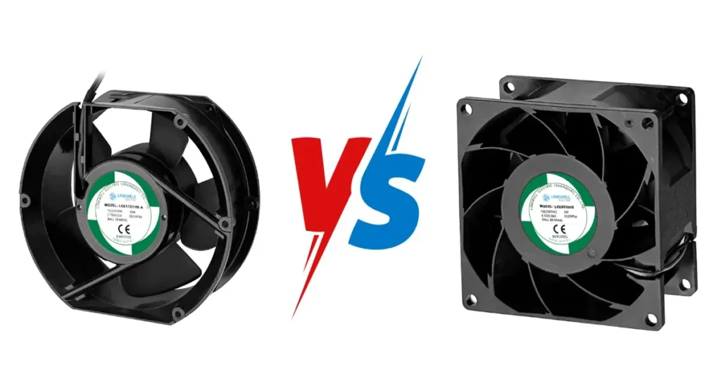
A square EC axial fan normally uses a square housing or frame with mounting holes near the corners. Compact 60 mm, 80 mm, 92 mm, 120 mm and similar equipment fans often use this form because the frame supports the motor, protects the blade envelope and fits a rectangular chassis efficiently.
A round EC axial fan may be supplied as a fan in a circular wall ring, a round plate fan, a motor-impeller assembly with an inlet ring, or a larger external-rotor axial fan intended for a circular opening. Those products are not interchangeable merely because their outer appearance is round. One may be a finished panel assembly while another requires the equipment manufacturer to provide the protective structure and airflow guide.
Nominal size is also inconsistent across formats. A ?250 mm? round fan may refer to impeller diameter, ring diameter or product series. A square fan may be identified by frame width and depth, such as 120 ? 120 ? 38 mm. Before comparing products, obtain the dimension drawing and identify:
- overall envelope and fan depth;
- impeller diameter and required blade clearance;
- panel cutout or ring inside diameter;
- mounting-hole pattern, fastener size and allowable orientation;
- connector location, cable exit and service space;
- airflow direction and direction of rotation.
LINKWELL lists EC axial fans in square and round frame configurations. The appropriate construction still depends on the project drawing and required operating point, so use the published range as a starting point rather than evidence that any two sizes are drop-in alternatives.
Does frame shape change airflow, pressure or efficiency?
Frame shape can influence the installed result, but it is rarely the main aerodynamic variable. Blade profile, hub ratio, tip clearance, inlet radius, guard blockage, motor supports and speed all affect the pressure-airflow curve. A well-integrated square fan can outperform a poorly installed round fan, and the reverse is equally possible.
The key issue is how much of the impeller’s annular flow area remains open. Axial fan blades do most of their work away from the hub. A small circular cutout, a dense guard or a heat exchanger that covers the blade tips can waste the most productive part of the swept area. A large opening with unsealed bypass gaps can also underperform because air recirculates around the frame instead of crossing the component you want to cool.
A round wall ring can provide a smooth approach to the blade and control tip clearance. A square housing can perform a similar function if its inlet geometry is designed properly. Four unused corner areas on a square frame do not create ?free airflow?; they may contain structure, electronics or mounting material. Conversely, the missing corners of a round frame do not automatically reduce performance if the assembly seals correctly to a circular opening.
Compare fan curves at the same airflow, static pressure, voltage, speed and air density. Then compare input power and sound under equivalent test conditions. The article on how to read a fan curve explains why free-air CFM and maximum pressure cannot be used as a single operating point.
Mounting, cutout and sealing differences
Square frames are convenient on flat sheet-metal panels. The hole pattern is easy to locate, the frame provides four reaction points, and a gasket can follow the perimeter. You should still check panel stiffness. A large thin panel can amplify vibration even when the fan itself is balanced.
Round fans suit circular ducts and rings, but their mounting flange may be wider than the impeller diameter. Some models use several flange holes, others use brackets, clips or a full mounting plate. The surrounding equipment must resist fan torque and vibration without distorting the ring. Distortion can change blade-tip clearance and create rubbing or noise.
Sealing deserves its own drawing. If a square fan is fitted over a round hole, the corners may be harmless solid frame?or they may become leakage paths, depending on construction. If a round fan is mounted in a square panel opening, the uncovered corners must be closed. Air that loops from discharge back to inlet reduces net system airflow even though the fan continues to move air locally.
Also account for protection. A guard, finger screen or filter can be required for safety and ingress control, but every accessory adds blockage and pressure loss. LINKWELL’s guide to axial fan accessories covers guards, filters, louvers, gaskets and mounting hardware. Use the accessory’s net free area and pressure-drop data rather than assuming an open-area percentage tells the whole story.
Important: Never enlarge a cutout or remove a guard simply to recover airflow without completing the required mechanical-safety and product-compliance review.
Noise and inlet conditions
Aerodynamic noise often comes from the installation rather than the EC motor. An obstacle close to one side of the inlet loads the blade unevenly once per revolution. That interaction can create a tonal sound that is far more noticeable than a small change in broadband dBA.
Round wall rings are often used because a smooth inlet radius helps the air enter the impeller uniformly. Square compact fans can also have shaped inlet edges, but a stamped panel aperture placed directly against the blade may behave differently from the catalog test setup. On either format, cable bundles, structural ribs, filters and heat-exchanger headers should not crowd one sector of the inlet.
Manufacturer installation guidance consistently warns that inlet and outlet obstructions reduce fan performance. AMCA describes these losses as fan system effect: nonuniform flow, swirl and turbulence near the fan can reduce airflow and increase energy, noise and vibration.
If acoustic performance matters, ask for sound-power data and the measurement standard, not only a single sound-pressure value. Sound pressure depends on distance, room absorption and installation. Test the final assembly at the required duty point and control signal. A fan that is quiet in free air can become objectionable when a grille, coil or partial blockage shifts its operating point.
Where each frame usually works best
| Application | Common starting format | Design questions that decide the choice |
|---|---|---|
| Electrical cabinet or control panel | Square compact EC axial fan | Panel cutout, filter loss, IP strategy, depth and wiring access |
| Telecom cabinet or power electronics | Square or round, depending on chassis architecture | Hot-swap method, redundancy, speed feedback and airflow zoning |
| Refrigeration condenser or evaporator | Round ring or plate axial fan | Coil face coverage, spacing, recirculation and outdoor protection |
| HVAC module or circular duct | Round frame or wall-ring fan | Duct connection, inlet transition, service access and sound target |
| Heat exchanger built into a rectangular plenum | Either | Fan-array layout, plenum uniformity, bypass sealing and coil pressure drop |
| Replacement of an existing OEM fan | Existing geometry unless redesign is approved | Hole pattern, depth, electrical interface, curve and certification impact |
These are starting points, not rules. For example, a round EC fan may be the right answer in a cabinet built around a circular intake, while a square fan array can work well across a rectangular coil face. The final choice should be supported by the installed pressure-airflow requirement and the mechanical interface.
If you are still deciding whether the airflow should be axial at all, compare an axial fan with a centrifugal fan. A frame-shape comparison cannot solve a system that actually needs a much steeper pressure curve or a 90-degree discharge.
How to compare two candidate fans
Start by marking the required operating point on both performance curves. The curves must use the same pressure basis and comparable air density. Record speed, input power and current at that point, not only at nominal voltage or maximum speed.
Next, overlay the dimension drawings on your equipment layout. Check the inlet opening, discharge opening, mounting pattern, fastener access, cable bend radius and removal path. A lower-profile fan is not useful if technicians cannot unplug it or remove the guard.
Then review the electrical interface. Confirm supply-voltage range, inrush behavior, protective earth where required, PWM or 0?10 V input characteristics, tachometer or alarm output and fault response. EC fans do not share one universal connector or control pinout. The EC fan wiring guide explains the checks that belong on the interface sheet.
Finally, compare environmental and compliance requirements: operating temperature, humidity, dust and water exposure, insulation class, approvals, flammability requirements and expected life at the actual operating point. IP rating applies to a defined product enclosure and test condition; it does not automatically make the finished panel opening equally protected.
A useful engineering comparison table has one row per requirement and four result columns: required, round candidate, square candidate and evidence. ?Looks compatible? should never be the evidence. Use a drawing, curve, certificate, test report or written supplier confirmation.
Retrofit checks before you change frame shape
A retrofit is not complete when the new fan spins. It is complete when the equipment maintains its thermal, acoustic, electrical and safety requirements across the expected operating range.
- Measure the existing cutout, hole centers, panel thickness, fan depth and clearance to nearby parts.
- Record the old fan’s actual operating voltage, control signal, speed feedback and alarm logic.
- Estimate the real system resistance with the normal guard, filter and heat exchanger installed.
- Compare old and new curves at that resistance, using the same pressure definition.
- Seal unused portions of the opening and prevent discharge-to-inlet recirculation.
- Check blade clearance, guard spacing, cable routing and removal access.
- Run a prototype thermal test at high load, high ambient and the dirty-filter condition.
- Measure temperature, speed, current, airflow or pressure and abnormal tonal noise.
Do not assume EC control will behave identically after a swap. Some fans run at maximum speed when the control lead is open; others stop or use a configured fallback. If the equipment relies on a safe default, verify it by disconnecting the control signal during prototype validation.
Key takeaway: A round-to-square or square-to-round change is an equipment redesign, not a cosmetic substitution. Validate the full airflow path before releasing it for production.
For new OEM projects, LINKWELL can review the envelope, duty point, electrical interface and control requirement before prototypes are built. That is the right stage to decide whether a standard frame or a customized mounting structure is justified.
FAQ
Is a round EC axial fan more efficient than a square fan?
Not by shape alone. Efficiency depends on the motor, drive, impeller, inlet geometry, tip clearance and operating point. Compare tested input power and airflow-pressure performance in equivalent installations.
Does a square frame move more air because it has more area?
No. The impeller swept area and system resistance determine useful airflow. The square corners usually contain housing or mounting structure; they are not additional active blade area.
Can I mount a round fan over a square hole?
Only if the mounting is structurally sound, the uncovered corners are sealed, the blade and guard clearances are safe, and the installed performance is validated. An adapter plate is often required.
Can I replace a square fan with a round EC fan of the same diameter?
Nominal diameter is not enough. Check cutout, hole pattern, depth, airflow curve, connector, control behavior, environmental rating and certification impact.
Which frame is better for a heat exchanger?
The better frame is the one that gives uniform coverage, limits bypass, fits the plenum and meets the duty point with acceptable power and noise. Round ring fans are common on circular coil openings; square arrays can suit rectangular faces.
Are round and square EC fans wired the same way?
No universal rule exists. Frame shape does not determine wiring. Always use the exact model’s wiring diagram and confirm power, protective earth, control and feedback terminals.

