
A cable tie slips into a fan, a bearing tightens, or debris prevents the rotor from turning. The fan still has power, but airflow falls to zero. What happens next depends on the exact motor and driver design. Some fans reduce or interrupt the motor drive, some report a fault, some attempt to restart, and some provide only limited protection.
Fan locked rotor protection is the part of the design intended to reduce prolonged electrical and thermal stress on the fan when the rotor cannot turn. It does not keep the equipment cool, remove the obstruction, or prove that the system has detected the failure. Those jobs require separate monitoring and a planned equipment response.
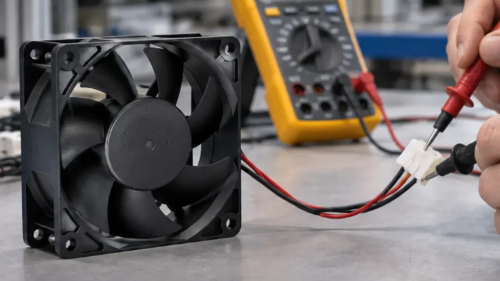
What Fan Locked Rotor Protection Actually Does
In a brushless DC or EC fan, the driver repeatedly energizes the motor windings in step with rotor position. If the blade is physically blocked, the bearing cannot turn, or the motor cannot complete commutation, the expected rotation feedback disappears. A protection circuit can then change the way the windings are driven so the fan is not left under the same electrical stress indefinitely.
The protective response may be current limiting, drive shutdown, intermittent retry, or a combination of these methods. The important word is may. “Locked rotor protected” does not define one universal circuit, delay, current level, or restart sequence. Those details must be confirmed for the exact fan model.
Locked rotor protection is also narrower than complete equipment protection. It can help the fan survive a blocked condition, but the heat load inside a power supply, enclosure, telecom unit, or server may continue. The host equipment still needs a way to recognize lost cooling and move to an alarm, derating, backup-fan, or shutdown state when required.
Note: A protected fan can still be a failed cooling path. Treat fan survival and equipment thermal safety as two separate design questions.
What Happens When a Cooling Fan Is Locked?
The first consequence is simple: useful airflow disappears or falls close to zero. Even if the fan electronics remain powered, the heat sink, filter, cabinet, or power module no longer receives the intended air movement. Component temperature may not rise immediately because the equipment has thermal mass, but the available response time depends on the heat load and the thermal design.
Inside the fan, a stationary rotor no longer produces the normal sequence of Hall transitions or back-electromotive-force information used for commutation. If the driver continued applying normal winding current, the coil and switching devices could experience prolonged heating. A protected design changes that condition after its lock criteria are met.
| Part of the system | What a rotor lock can cause | What must be checked |
|---|---|---|
| Fan motor and driver | Abnormal electrical and thermal stress | Protection method, lock current, shutdown behavior and restart sequence |
| Power supply | Steady or pulsed current during protection and retry | Terminal voltage, current waveform and supply protection response |
| Cooled equipment | Loss of airflow and rising component temperature | Alarm threshold, thermal margin, derating and safe shutdown |
| Control system | Missing speed pulses or a changed alarm output | Signal polarity, pull-up, debounce time and fault logic |
Do not assume that locked-rotor current is always higher than the normal running current. Some protected fans shut the drive off and retry periodically, so a meter may show an average value that hides short current pulses. The relevant information is the time behavior at the fan terminals, not only one current number.
How Does Fan Locked Rotor Protection Work?
The internal sequence normally has two jobs: decide that rotation has not occurred, then reduce motor-drive stress. The implementation varies with motor topology and driver electronics, so the following mechanisms should be treated as design patterns rather than a promise about every fan.
Lock detection
The driver can look for missing Hall-sensor transitions, missing commutation events, absent back-EMF information, or another indication that the rotor has not advanced. A short delay is usually necessary because the fan also begins at zero speed during a normal start. The datasheet may state a detection time, but many fan datasheets describe only the resulting protection behavior.
Current limiting
Some designs limit the winding current while trying to produce enough torque to start or recover. Current limiting can reduce stress, but it does not by itself tell the equipment controller that airflow has failed. Its threshold and timing are properties of the internal driver and cannot be inferred from the fan’s rated running current.
Motor shutdown or drive-off time
Another common response is to disable or greatly reduce the output drive after a lock is detected. The winding then has time to cool. A fan described as “locked rotor protected” may stay off until power is cycled, wait for an external command, or enter an automatic retry sequence. The protection description should make that distinction clear.
Automatic restart
A fan with auto restart periodically applies drive again to see whether the obstruction has cleared. If rotation returns, normal commutation resumes. The retry interval, drive duration, torque and maximum permitted lock time are model-specific. Repeated restart can also create a pulsed load on the power supply, so it should be observed during system validation.
Locked-rotor alarm or RD signal
An RD or locked-rotor output reports a state to the host controller. Depending on the design, its logic changes after a defined period without rotation and returns when rotation resumes. Confirm whether the output is open-collector or another interface, which voltage it can tolerate, whether an external pull-up is required, and whether the active state is high or low.
Protection and an RD output are related features, but one does not automatically guarantee the other. A fan can protect itself without exposing a fault signal, and a controller can detect missing rotation from feedback even when the fan’s internal protective method is different.
Locked Rotor Protection vs Locked Rotor Detection
These terms are often placed next to each other in a datasheet, but they answer different questions.
| Function | Main purpose | What the equipment receives | What it does not prove |
|---|---|---|---|
| Locked rotor protection | Reduce prolonged stress inside the fan | Usually no direct information unless a separate output is provided | That cooling continues or the host knows about the fault |
| Locked rotor detection or RD | Report a stopped or locked state | A logic state defined by the fan interface | Exact RPM or actual airflow |
| FG or tachometer output | Provide rotation pulses | A pulse frequency related to speed | That the airflow path is clear |
| System thermal protection | Protect the cooled equipment | An alarm, derating action, backup-fan command or shutdown | That the fan itself will survive a lock |
An RD signal is usually easier for a controller to interpret as a binary fault. An FG signal carries more speed information, but firmware must decide how long missing or slow pulses can persist before declaring a failure. The fan tachometer signal guide explains pulse counting, pull-ups and the limits of speed feedback in more detail.
Neither RD nor FG measures airflow. A fan can rotate while a filter is blocked, the blade turns in the wrong direction, or the inlet is starved. If the safety objective is adequate cooling, use temperature, airflow, pressure, or another system-level measurement in addition to rotation status where the risk justifies it.
Why Locked Rotor Protection Matters in Industrial Equipment
In an open bench test, a stopped fan is obvious. Inside operating equipment, the same failure can be hidden until a temperature alarm appears. That is why locked rotor behavior matters most when the fan is difficult to inspect, the heat load continues after airflow is lost, or a single fan supports a critical component.
In an electrical enclosure, a cable, loose label, filter debris, or installation error can interfere with the blade. In a power supply, telecom unit, automation controller, or server, a bearing fault or foreign object can remove cooling while the electronic load remains active. The fan’s protection can reduce the chance that the fan motor becomes an additional heat source, but it does not replace a thermal response for the equipment.
The required system action should follow the consequence of lost airflow. A noncritical display enclosure may only need a maintenance alarm. A high-power converter may need load derating or shutdown. A system designed for continued operation may need a monitored standby fan or N+1 arrangement. The fan redundancy guide explains why adding a second fan is only useful when the airflow path, controller logic, and failure test are also designed for it.
Protection is also valuable during assembly and service. A harness routed too close to the rotor or a misplaced finger guard can create a lock before the equipment leaves production. A controlled end-of-line check can catch those integration problems, provided the test method is safe and approved for the selected fan.
Does Every DC, EC, or AC Fan Have This Protection?
No. Protection and signal options vary by fan family, size, voltage, motor driver and customer configuration. A label such as “brushless DC” or “EC” describes the motor technology; it does not list every protection feature inside that model.
| Fan type | Possible protection approach | What to verify |
|---|---|---|
| Brushless DC fan | Electronic lock detection, current control, drive shutdown and optional auto restart | Exact protection sequence, RD or FG option, logic interface and test conditions |
| Low-voltage EC fan | Integrated electronic protection and diagnostic functions, depending on the controller | Supply range, enable or speed command, fault output and restart policy |
| Mains-powered EC fan | Controller-managed protection, alarms or digital fault reporting on some models | Mains input, control interface, alarm definition and whether faults latch or reset |
| AC fan | Impedance protection, thermal protection, a thermal switch, or another motor-specific method | Locked-rotor rating, reset behavior, permitted duration, voltage and frequency |
“Fan stall protection” can also be ambiguous. In compact cooling-fan documentation it may refer to a non-rotating rotor. In aerodynamic discussions, stall describes unstable airflow over the blade while the rotor may still be turning. Keep the electrical locked-rotor requirement separate from the fan stall and surge operating condition.
When a protection feature is important to the equipment safety case, obtain it in the exact part-number specification or approved drawing. A feature shown as optional on a product-family page should not be assumed to be present in every shipped configuration.
How to Check a Fan Datasheet
Start with the exact part number, not a family description. If the public datasheet is brief, request the detailed electrical specification, wiring diagram, alarm timing information, and the conditions used for the locked-rotor test.
| Datasheet item | Question to answer | Why it matters |
|---|---|---|
| Protection description | Does the fan limit current, switch the drive off, retry, or require a reset? | Defines the fan’s behavior while blocked |
| Locked-rotor current | Is the value maximum, typical, peak, average, or measured after protection activates? | Determines the real power-supply load |
| Lock detection time | How long must rotation be absent before protection or an alarm is asserted? | Sets the earliest reliable system response |
| Auto-restart timing | How often does the fan retry, and under what supply and command conditions? | Affects current pulses, recovery time and fault logging |
| RD or alarm output | What are the active state, voltage limit, sink or source rating, and pull-up requirement? | Prevents incorrect controller wiring and logic |
| FG output | How many pulses represent one revolution, and what counts as a fault? | Supports speed monitoring but needs firmware logic |
| Locked-rotor endurance | Is continuous lock permitted, and at what voltage and ambient temperature? | Defines the tested boundary rather than an assumed one |
| Release behavior | Does the fan resume automatically, need a power cycle, or need an enable command? | Determines recovery after the obstruction clears |
Tip: If a datasheet only says “locked rotor protected,” ask for the lock current waveform, alarm logic and restart behavior. The phrase alone is not enough to design the power supply or fault response.
Also confirm whether the stated values apply at rated voltage only or across the full operating voltage and temperature range. Protection behavior near undervoltage, at a low PWM command, or during a slowly rising supply can differ from a rated-voltage bench test.
How to Select a Fan with Protection Features
Selection begins with the equipment response, not the feature label. Work through the following sequence before approving a sample.
- Define the fault that matters. Decide whether you need the fan to survive a blockage, the controller to detect a stopped rotor, the equipment to remain within a safe temperature, or all three.
- Confirm the internal protective response. Obtain the shutdown, current-limiting, retry and reset behavior for the exact model.
- Choose the right status signal. Use RD when a binary locked or running state is sufficient. Use FG when the controller must compare actual speed with a target. Some systems use both, but only when the model provides both outputs.
- Match the electrical interface. Check output topology, logic voltage, pull-up, polarity, leakage current, cable length and controller input thresholds. Do not select from wire color alone.
- Check the supply under every state. The source must support normal startup, running current, lock behavior and any periodic restart pulses without collapsing or tripping unexpectedly. The fan power supply sizing guide covers voltage drop and transient-current margin.
- Define the system response. Set fault timing, logging, derating, backup-fan and shutdown actions according to the equipment risk.
- Validate the installed assembly. Test production wiring, guards, filters, controller firmware and the real thermal load rather than approving the fan on a free-air bench alone.
For a LINKWELL fan selection, state the required supply, fan size, airflow and pressure duty, control input, feedback or alarm signal, restart preference and equipment response to lost cooling. LINKWELL can then confirm which functions are available for the proposed model instead of assuming that every DC, AC or EC fan uses the same protection package.
How to Validate Locked Rotor Behavior in the Final Equipment
A locked-rotor test is useful only when it reproduces a defined fault without creating an uncontrolled mechanical or electrical hazard. Confirm that the fan supplier permits the test, use a guarded fixture or a specified non-damaging blocking method, and never stop a rotating blade by hand.
- Record the baseline. At the intended supply and control command, measure terminal voltage, running current, speed feedback and the equipment temperature at representative load.
- Apply the defined obstruction safely. Record the time from lost rotation to drive protection and to the RD or firmware fault indication.
- Observe the supply. Capture current with enough time resolution to see shutdown and retry pulses. Verify that shared rails and upstream protection remain stable.
- Check the equipment response. Confirm the alarm, derating, backup cooling or shutdown occurs before critical component limits are reached.
- Remove the obstruction. Verify whether the fan restarts automatically or requires the documented reset action, then confirm normal speed and airflow return.
- Repeat at relevant boundaries. Include the lowest and highest permitted supply, cold and hot conditions, minimum speed command, and realistic filters or guards where these conditions affect the application.
Startup and recovery are not identical tests. After an auto-retry pulse, the power rail can respond differently from a normal power-on event. Compare the behavior with the cooling fan startup current measured during ordinary start, and make sure the controller does not misclassify a valid startup delay as a fault.
Note: A blocked-rotor endurance test can damage a fan that was not designed or approved for it. Use the exact model’s test limits and stop criteria rather than inventing a duration.
Common Selection and Integration Mistakes
| Mistake | Why it causes trouble | Better approach |
|---|---|---|
| Assuming protection means the system is safe | The fan may survive while the cooled components continue heating | Define a separate thermal alarm, derating or shutdown response |
| Treating RD and FG as interchangeable | One is normally a status output; the other is a pulse train | Match the signal type and firmware to the required information |
| Using rated current to size the fault condition | Protection and retry can create a different current waveform | Review lock and restart data, then measure the final assembly |
| Assuming every fan auto restarts | Some designs latch off or need a power cycle or command | Confirm release behavior for the exact model |
| Ignoring low-speed control | A low PWM command or undervoltage state may change detection and restart behavior | Test at the minimum approved command and supply |
| Blocking the blade by hand | It creates an avoidable injury and equipment-damage risk | Use a guarded, documented test fixture |
| Approving only the fan | The final guard, cable routing, filter and firmware can introduce new failure modes | Repeat the fault test in a representative production assembly |
The most useful specification is not a long feature list. It is a clear sequence showing what the fan does, what signal the controller sees, how the equipment responds, and how the system recovers after the blockage is removed.
Frequently Asked Questions
What causes a fan rotor to lock?
Common causes include foreign objects, cable or label interference, a damaged or contaminated bearing, ice or debris, mechanical deformation, incorrect assembly, and an internal motor or driver fault. A stopped rotor should be investigated rather than repeatedly restarted without finding the cause.
Can a locked fan restart automatically?
Some fans can. An auto-restart design periodically retries the motor and returns to normal operation after the lock is removed. Other models remain off until power is cycled or an enable command changes. Confirm the exact behavior and timing in the model documentation.
What is RD on a cooling fan?
RD usually means rotation-detect or locked-rotor status output. It provides a logic state rather than a continuous RPM value. The active polarity, electrical output type, pull-up requirement and delay are not universal, so the wiring diagram is part of the specification.
Is locked rotor protection the same as overcurrent protection?
No. Overcurrent protection reacts to an electrical current condition. Locked rotor protection reacts to the absence of expected rotation or commutation and may then limit current or shut the drive down. A fan driver can include both functions, one function, or a combined strategy.
Do all brushless DC fans have locked rotor protection?
No. Brushless construction does not guarantee a particular protection circuit, alarm output or auto-restart function. Check the approved specification for the exact fan model and option code.
Can PWM still work with locked rotor protection?
Yes, a PWM-controlled fan can also include locked-rotor protection. However, the protection must distinguish a genuine lock from an intentionally low or zero command. Confirm the permitted PWM frequency and duty-cycle range, minimum-speed behavior, lock detection timing and restart response.
Does locked rotor protection prevent equipment overheating?
Not by itself. The feature is mainly intended to reduce stress inside the fan. The equipment still needs enough thermal margin and an appropriate response to lost airflow, such as an alarm, derating, redundant cooling or safe shutdown.
LINKWELL supplies industrial DC, AC and EC fan solutions with protection, control and feedback options that vary by model. For selection, share the supply voltage, fan size, operating airflow and pressure, controller interface, required fault signal, restart preference and the action your equipment must take after airflow is lost.

