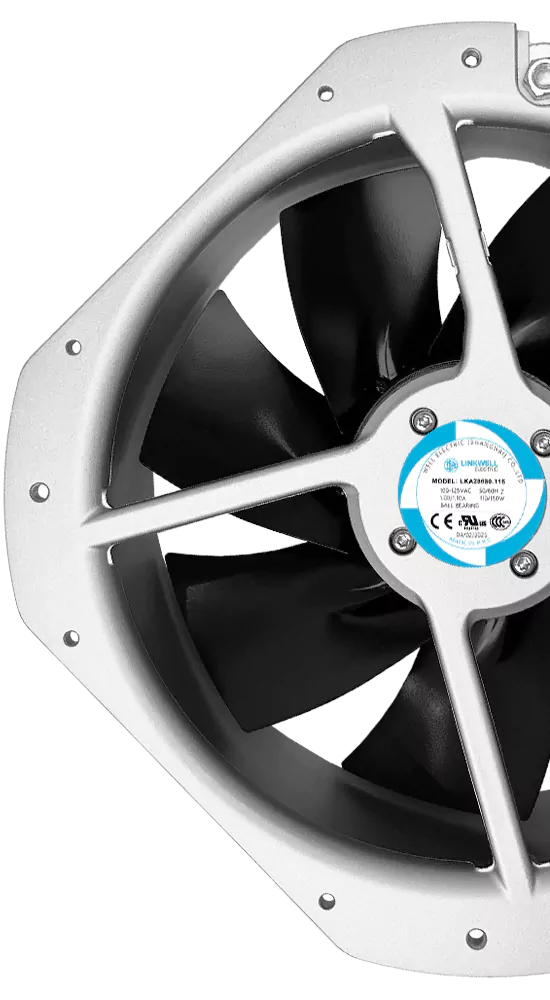
A telecom cabinet cooling fan should be selected from the cabinet’s heat load, allowable temperature rise, airflow path and system resistance—not from free-air CFM alone. Outdoor exposure, filter loading, supply voltage, speed control, alarm feedback and fan redundancy also have to match the real installation.
This matters because a fan that looks adequate on a datasheet can deliver much less airflow after it is installed behind a filter, grille or heat exchanger. In a remote 5G base station, the cost of that mismatch is not limited to a warm cabinet. It can lead to repeated thermal alarms, speed throttling, shorter component life and an unnecessary service visit.
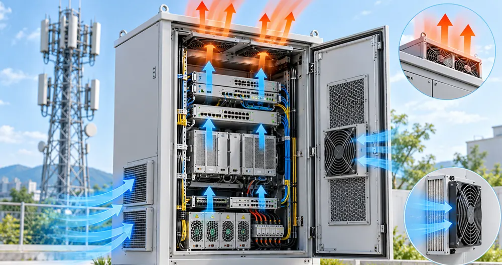
What Does a Telecom Cabinet Cooling Fan Need to Do?
The fan’s job is to move enough air through the actual cabinet to keep sensitive equipment within its permitted temperature range. Depending on the cabinet architecture, it may introduce filtered outside air, circulate air through an internal heat exchanger, move air across power modules, or support a separate cooling unit.
That distinction should be settled before a fan is selected. An open-loop ventilated cabinet exchanges air with the environment, so dust, humidity and filter pressure drop become important. A closed-loop cabinet keeps internal and external air paths separate, so the fan may need to overcome a heat exchanger core rather than a simple louver. A circulation fan inside a sealed cabinet cannot remove heat by itself; it only improves heat transfer to another surface or cooling device.
Note: A fan does not lower the air temperature below the temperature of the air or surface available for heat rejection. If the outdoor ambient can exceed the permitted cabinet temperature, ventilation alone may not be sufficient.
Start With the Cabinet, Not the Fan Catalog
Before comparing fan models, define the equipment and the operating environment. The most useful starting information is the maximum internal heat dissipation, permitted component or cabinet temperature, worst-case ambient temperature, cabinet dimensions, inlet and outlet locations, filters, grilles, heat exchangers and expected altitude.
Also identify whether the stated heat load represents normal traffic, a short peak or a worst-case continuous condition. A fan sized around a light laboratory load may appear successful during commissioning but lose margin when radio, transmission and power-conversion equipment operate together in hot weather.
Telecom equipment is used in protected rooms, street cabinets, rooftop installations and other environments with very different temperature, humidity, particulate and mechanical conditions. The ETSI Environmental Engineering committee treats location, power infrastructure, environmental conditions and thermal management as related design inputs rather than isolated fan specifications.
Calculate the Required Airflow From the Heat Load
The required airflow depends on how much heat must be removed and how much air-temperature rise the equipment can tolerate. A smaller permitted temperature rise requires more airflow for the same heat load. The calculation provides a starting point, not the final fan operating point.
Use the cabinet’s dissipated heat, not the nameplate input power of every installed device added together without review. Some input power leaves as useful output, while other devices may not operate at full load simultaneously. At the same time, do not ignore power supplies, rectifiers, batteries, network switches or auxiliary electronics that add heat inside the enclosure.
After calculating the theoretical airflow, add engineering margin for filter loading, manufacturing variation, altitude, airflow leakage and future equipment changes. Margin should be based on known uncertainty rather than an arbitrary oversized fan. Excess airflow can raise noise, power consumption and dust intake without solving a poor air path.
System Resistance Determines the Real Airflow
A fan performance curve shows the relationship between airflow and pressure. The cabinet has its own system curve, created by every restriction in the air path. The operating point is where the fan curve and the system curve meet.
Common sources of resistance in telecom cabinets include:
- Inlet filters and filter media loaded with dust
- Perforated panels, louvers and rain hoods
- Finger guards and protective screens
- Narrow ducts and abrupt turns
- Densely packed circuit boards and cable bundles
- Heat exchanger cores and internal baffles
- Small outlet openings or obstructed exhaust paths
Free-air airflow is measured near zero static pressure. It does not represent the airflow through a working cabinet. A high free-air CFM value can therefore be misleading when two fan candidates have different pressure capability.
For the underlying selection method, see How to Read a Fan Curve and Fan System Effect.
Design a Clear Airflow Path Through the Equipment
Useful airflow must pass through or across the parts that create heat. Air that enters the cabinet and immediately escapes through a nearby opening contributes little to component cooling. The same is true when a large gap lets air bypass a heat sink, rectifier or radio module.
Place the intake and exhaust so air crosses the complete thermal path. Use baffles or shrouds when they are needed to prevent bypass. Keep wiring away from fan inlets and avoid mounting a wall, filter frame or cable bundle directly against the fan. The fan also needs enough inlet and outlet clearance to avoid uneven loading and added noise.
Temperature sensors should be placed where they reveal equipment risk, not simply where the incoming air is coolest. A single sensor close to the fan inlet can report an acceptable temperature while a stagnant region behind a module continues to overheat.
Open-Loop and Closed-Loop Telecom Cabinet Cooling
| Cooling arrangement | How it works | Main fan-selection concern |
|---|---|---|
| Open-loop ventilation | Outside air enters the cabinet and heated air is exhausted | Filter loading, dust, humidity, water paths and positive or negative pressure |
| Closed-loop heat exchanger | Internal and external air circuits remain separated | Pressure drop through the heat exchanger and coordination of both air circuits |
| Internal circulation | Air is redistributed inside the enclosure | Removing hot spots without claiming that circulation alone rejects heat |
| Hybrid or active cooling | Fans support an air conditioner, heat exchanger or other cooling device | Matching airflow, controls and fault behavior with the complete thermal system |
The correct fan cannot be chosen independently of this architecture. For example, an axial fan may be appropriate for a relatively open air path, while a higher-pressure fan or blower may be needed when the flow must pass through a compact heat exchanger or restrictive duct. The decision should be based on the required operating point rather than the fan category alone.
Environmental Conditions That Change Fan Selection
Temperature
Check both the maximum and minimum temperatures at the fan location. The temperature near an exhaust fan may be higher than the outdoor ambient because it receives heated cabinet air. At low temperature, startup behavior, bearing lubricant and condensation after a temperature transition may become relevant.
Do not apply a general fan-family temperature claim to every model. Confirm the operating-temperature range and any performance limitations for the exact candidate. The Cooling Fan Operating Temperature Range guide explains how to read this specification.
Dust and Filter Loading
A clean filter has one pressure drop; a filter near its service limit has another. The fan must be evaluated against a realistic loaded-filter condition. If maintenance intervals are long or site access is difficult, monitoring filter condition or cabinet temperature may be more useful than simply installing a faster fan.
Humidity and Condensation
High relative humidity and actual condensation are different conditions. Condensation can occur when a cold fan or cabinet surface falls below the dew point. Outdoor equipment that cools overnight and is then exposed to warmer humid air can be at risk even when it has not been directly sprayed with water.
An enclosure or fan IP rating addresses defined access, dust and water-ingress tests. It does not by itself describe every condensation cycle, corrosive atmosphere or final cabinet installation. Environmental protection must be reviewed at fan, connector and equipment level.
Altitude
Lower air density changes the relationship between airflow, cooling capacity and pressure. If the base station operates at significant altitude, do not assume that a sea-level thermal result will transfer unchanged. Validate the installed equipment under the intended environmental range or apply a documented derating method.
Select the Correct Supply Voltage and Electrical Interface
Telecom power architectures often use nominal DC supplies, but the fan must be matched to the actual voltage range at its terminals. A nominal 48 V system does not mean that every 48 V fan is compatible with every operating, charging or transient condition. Verify the minimum and maximum steady supply, startup behavior, wiring losses and protection arrangement.
If the cabinet uses another voltage, avoid adding an unnecessary converter solely because a familiar fan model was chosen first. Compare the complete electrical architecture, efficiency, serviceability and available fan options.
The article 24V vs 48V DC Cooling Fan provides a focused comparison, while Fan Operating Voltage Range explains the difference between rated, starting and permitted operating voltage.
Speed Control, Monitoring and Alarm Signals
Continuous full-speed operation is simple, but it may use more power and create more noise than necessary during low thermal load. A compatible PWM or other speed-control input lets the equipment adjust fan speed according to temperature or system demand. The controller should still maintain enough minimum airflow for the least-cooled component and should handle startup reliably.
FG or tachometer feedback provides pulses related to rotation. RD or alarm output typically indicates a defined abnormal condition. These signals are not interchangeable, and their electrical interfaces vary by fan model. The host controller needs the correct pull-up, logic voltage, pulse interpretation and fault thresholds.
A useful alarm strategy checks more than whether a wire changes state. It defines how long a fault must persist, what the controller does next, how it distinguishes a low commanded speed from a failed fan, and whether an alarm remains visible after an automatic restart.
For detailed interface design, see Fan Tachometer Signal, Fan RD Signal and PWM Fan Frequency.
When Does a Telecom Cabinet Need Fan Redundancy?
Redundancy is useful when a single fan failure cannot be allowed to remove the required cooling. In an N+1 arrangement, the remaining fans must still meet the minimum thermal requirement after one fan is unavailable.
Simply installing an extra fan does not prove redundancy. When one fan stops, air can flow backward through the failed opening, and the pressure-flow operating point of the remaining fans changes. The controller must detect the fault, command the remaining fans as intended and issue an actionable alarm.
Test the real failure state by stopping or disconnecting one fan while the cabinet is operating at a defined load and ambient condition. Measure component temperatures and observe alarm behavior. The design method is explained in Fan Redundancy: N+1 Cooling Design and Failure Testing.
Axial Fan or Centrifugal Blower?
An axial fan is often efficient and compact when air moves relatively straight through a cabinet with moderate restriction. A centrifugal blower is useful when the air path requires a side outlet, concentrated flow or greater pressure capability. Neither is automatically better for all telecom equipment.
Compare candidates at the required airflow and static pressure. Then review size, noise, power, control interface, installation clearance and service access. A blower with a suitable curve can outperform an axial fan in a restrictive path, while an oversized blower in an open cabinet may add cost and noise without improving component temperatures.
How to Validate the Fan in the Actual Cabinet
Bench testing confirms that a fan runs, but installed validation confirms that the cabinet cools. A practical test should represent the intended equipment load, supply voltage, filter condition, ambient range and control settings.
Record:
- Ambient and inlet-air temperature
- Temperatures at critical modules and known hot spots
- Fan voltage, running current and commanded speed
- FG or RD response
- Airflow or pressure at defined measurement locations
- Noise and vibration in the installed structure
- Results with a loaded filter or simulated restriction
- Results after one fan is stopped when redundancy is required
Do not move a temperature probe between tests without documenting the location. Small position changes can make comparisons unreliable. Allow the system to approach a stable thermal condition before deciding whether the fan has passed.
Information to Send a Cooling Fan Manufacturer
A useful selection request includes more than a desired fan size. Provide the cabinet layout, maximum heat load, ambient and altitude range, target temperatures, available fan opening, airflow path, estimated pressure drop, filter and grille details, supply voltage range, control signals, noise limit, environmental exposure and redundancy requirement.
If a connector, lead length or airflow direction is fixed, include the mating part number and drawing. If the system already has a problem, describe the symptom—such as high outlet temperature, low installed airflow, repeated fan alarm or filter-related overheating—and provide the operating conditions when it occurs.
LINKWELL can evaluate AC, DC and EC cooling fan options for telecom and communication equipment. Final recommendations depend on the confirmed operating point, electrical interface, environment and validation requirements of the specific project.
Frequently Asked Questions
What type of fan is used in a telecom cabinet?
Telecom cabinets may use DC or EC axial fans, centrifugal blowers or fans integrated into a heat-exchanger or cooling module. The correct type depends on required airflow, system resistance, supply voltage, outlet direction, control requirements and available space.
Is a 48V fan always required for a 5G base station?
No. A 48 V architecture is common in telecom equipment, but the fan must match the actual equipment supply and permitted voltage range. Some subsystems may use other voltages. Confirm the fan terminals, not only the cabinet’s nominal power-system label.
How much airflow does a 5G base station cabinet need?
There is no universal CFM value. Required airflow depends on the internal heat load, allowable temperature rise, ambient conditions, cabinet leakage and pressure drop through filters, grilles, heat exchangers and internal components.
Should a telecom cabinet use positive or negative pressure?
A filtered positive-pressure arrangement can help control where air enters an open-loop cabinet, but it must be designed with adequate exhaust area and enclosure requirements. Negative pressure may draw unfiltered air through gaps. The correct arrangement depends on the complete cabinet design rather than the fan direction alone.
How can a controller detect a failed telecom cooling fan?
The system can monitor FG speed pulses, an RD alarm output, fan current or temperature response. The method must match the fan’s signal specification and distinguish a commanded low speed from a genuine failure.
Does an IP-rated fan make an outdoor telecom cabinet weatherproof?
No. A fan rating applies to the defined fan construction and test conditions. Cabinet openings, filters, connectors, cable entries, drainage and installation orientation still determine the protection of the completed equipment.
Final Selection Advice
Select a telecom cabinet cooling fan from the required installed operating point and the worst credible environment. Confirm the air path, filter condition, voltage range, control interface and failure response before releasing the design. A fan should be approved because the cabinet passes its thermal and functional tests—not because the free-air CFM looks large enough.