
The old fan has become noisy, the original part is unavailable, or a buyer needs a second source before the next production run. The quickest search is usually by frame size and voltage. That may find a fan that fits the opening, but it does not prove that the equipment will cool correctly or communicate with its controller.
A reliable replacement cooling fan must match the job performed inside the equipment. That includes airflow at the real system resistance, electrical input, startup behavior, mounting, airflow direction, connector, speed control, alarm signals, temperature range and expected service life. The label is useful evidence, but it is rarely the complete specification.
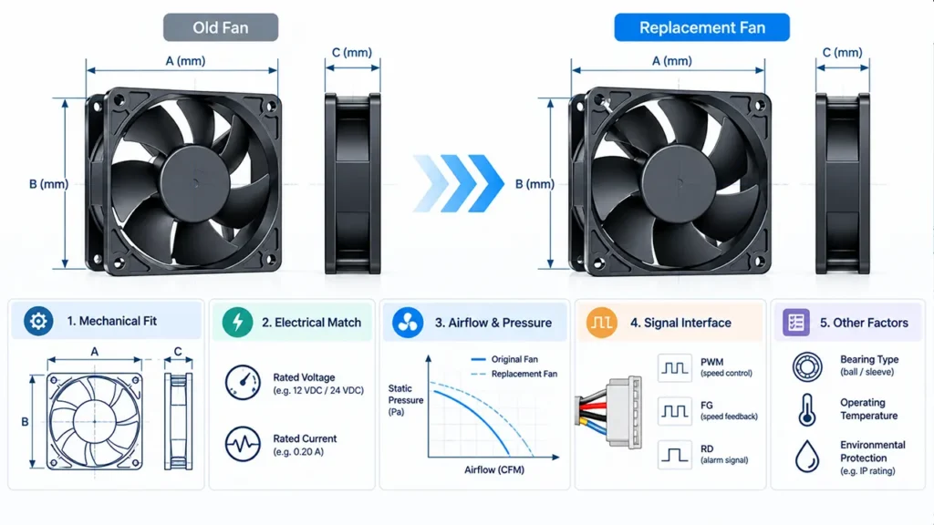
Why the Same Size and Voltage Do Not Guarantee a Safe Replacement
Two 120 x 120 x 38 mm, 24 VDC fans can have different blade geometry, motor control, speed, pressure curves, startup current and signal interfaces. Both may spin when connected to the same supply, yet one can deliver much less airflow after a filter or dense heat sink is added.
The reverse is also possible. A higher-speed replacement may provide enough cooling but create unacceptable noise, draw more current than the supply can support, or produce a tachometer signal the controller cannot read. A successful replacement therefore needs functional equivalence, not just physical similarity.
Note: Never approve a replacement only because it spins on the bench. The final decision should be based on electrical compatibility and a temperature test in the real equipment.
What a Replacement Cooling Fan Must Match
| Area | What to compare | What can go wrong |
|---|---|---|
| Mechanical | Frame size, thickness, hole spacing, airflow direction and cable exit | The fan cannot mount, the cable is pinched, or airflow is reversed |
| Electrical | AC/DC/EC input, rated voltage, operating range, frequency and current | The fan fails to start, overheats, or trips the supply |
| Aerodynamic | Airflow and static pressure at the required operating point | The fan looks adequate in free air but undercools the equipment |
| Control | PWM, voltage control, 0–10 V or other input behavior | Speed control is unstable or works over the wrong range |
| Feedback | FG/tachometer, RD/alarm output and logic interface | The controller reports a fan fault or cannot detect failure |
| Environment | Temperature, dust, moisture, vibration and duty cycle | Life or performance falls below the application requirement |
| Acoustics | Sound level, tone and installed resonance | The equipment becomes louder even when cooling is acceptable |
Start with the Equipment, Not the Old Part Number
The old fan provides a useful reference, but the equipment defines the real requirement. Record what the fan cools, where air enters and exits, which components set the temperature limit, and whether the fan runs continuously or only under high load.
If the original fan is still operating, capture the supply voltage at the fan, running current, speed signal, control command and component temperatures before removing it. These measurements are more valuable than a label photo alone because they describe how the fan works in the system.
Identify the Worst Thermal Condition
Use the highest expected ambient temperature, maximum equipment load, dirty-filter condition and any altitude requirement that matters to the product. A replacement validated only at room temperature may fail when the cabinet is hot or the filter has accumulated dust.
Map the Air Path
Follow the air through grilles, filters, heat sinks, card cages and outlet vents. Look for bypass gaps and recirculation. If the original air path is poor, selecting a stronger fan may hide the problem without solving it. The articles on fan system effect and cooling fan shroud design can help separate fan capacity from installation loss.
Check Mechanical Compatibility
Measure the outer frame, thickness, mounting-hole spacing and available space on both sides. Confirm the screw size, mounting method, cable length, cable exit and connector access. A thicker replacement may fit the panel opening but collide with a heat sink or reduce inlet clearance.
Airflow direction and rotation direction should be read from the drawing or markings, not guessed from blade appearance. Also check whether the original fan uses a gasket, guard, filter or special bracket. These parts can affect both fit and airflow.
Mounting orientation is relevant when the fan operates for long periods in a position different from its qualification condition. If orientation matters to the selected model, it should be confirmed before approval rather than discovered after field installation.
Match the Electrical Input
Fan Type and Rated Supply
First confirm whether the original is an AC fan, a low-voltage DC fan, or an AC-input EC fan. Similar-looking fans can require completely different power connections. For AC models, confirm voltage and frequency. For DC models, confirm polarity, rated voltage and the permitted operating voltage range.
A nameplate voltage is not the whole story. The fan must start and run across the equipment’s actual supply variation. The fan operating voltage range article explains the difference between rated, starting and operating voltage.
Running Current and Startup Current
The replacement’s running current must be compatible with the wiring, connector and power budget. Startup current also matters, especially when several DC fans start together or when the control supply uses fast overcurrent protection.
A fan that consumes less current during steady operation can still have a startup transient that causes the supply to fold back or reset. Measure the event with suitable equipment or obtain model-specific data instead of multiplying the running current by an assumed factor. See Cooling Fan Startup Current for a practical test approach.
Connector and Pin Assignment
A connector that physically mates can still have a different pin order. Verify each conductor from the datasheet or approved wiring drawing. Do not rely on wire color because color conventions vary between models and custom assemblies.
Record the connector series, housing, terminal, keying, pin assignment, cable length and any sleeve or locking requirement. The guide to cooling fan connector types explains why the interface should be specified as a complete assembly.
Match Airflow at the Real Static Pressure
Maximum airflow is normally measured near free-air conditions. Equipment adds resistance, so the installed fan operates at the intersection of the fan curve and the system curve. Filters, narrow vents, dense fins and cable bundles can move that point far from the advertised maximum CFM.
Compare the original and candidate pressure-flow curves at the expected system resistance. If the system curve is unknown, measure pressure or airflow with a repeatable fixture, or use the original fan as a thermal reference. The article How to Read a Fan Curve explains the operating point.
Do not reject a candidate only because its free-air value is slightly lower. It may deliver equal or better flow at the equipment’s pressure. Likewise, a higher free-air value does not guarantee better installed cooling.
Verify Control and Monitoring Signals
For a two-wire fan, power may be the only interface. Three- and four-wire fans may add speed feedback, locked-rotor alarm or PWM control. Industrial custom fans can use other arrangements, so the wire count alone does not define function.
For PWM control, compare the required frequency range, input voltage levels, polarity, duty-cycle response, minimum operating behavior and response at 0% duty cycle. For FG or tachometer output, check pulses per revolution, output circuit and pull-up requirements. For RD output, confirm which logic state represents normal rotation and which represents a stopped or locked rotor.
The controller may treat a missing or unexpected signal as a fault even when airflow is adequate. Validate the full interface during startup, speed changes, commanded stop and simulated fan blockage.
Consider Noise, Bearings and Environment
A replacement fan can pass the airflow test and still be unsuitable. Higher speed may introduce a tonal sound, excite a panel resonance or create turbulence against a nearby grille. Compare noise in the final assembly, not only the datasheet sound-pressure number.
Bearing type, operating temperature, mounting orientation and duty cycle affect service life. Environmental needs may also include dust, moisture, oil mist, salt exposure or vibration. An IP code alone does not prove compatibility with every contaminant or cleaning process.
Ask for evidence that applies to the exact model and option being considered. Avoid turning a general family feature into a claim about every variation.
A Practical Replacement Fan Workflow
- Photograph the old label, connector, wire order, mounting and airflow direction.
- Measure frame dimensions, thickness, hole spacing, cable length and available clearances.
- Record supply voltage at the fan, running current, control signal and feedback behavior.
- Identify the required airflow at the real system resistance or document the approved thermal result.
- Shortlist candidates that match mechanical, electrical, aerodynamic and environmental requirements.
- Test samples in the real equipment at worst-case load and ambient conditions.
- Check startup, control range, alarms, noise, vibration and temperatures.
- Freeze the approved part number, connector drawing, revision and acceptance criteria.
How to Validate a Replacement Sample
Use the original fan as a reference only if it is healthy and representative. Run the equipment long enough to reach a defined thermal condition, then compare critical component temperatures, inlet and exhaust temperatures, fan voltage, speed and noise.
Repeat the test at maximum load and expected high ambient. If a filter is used, include a realistic end-of-service pressure condition or an agreed restriction. For redundant systems, disconnect one fan and verify the failure response, alarm logic and remaining cooling capacity.
One passing sample does not define production acceptance. Agree which parameters will be checked during incoming inspection and which belong to design validation. Airflow tolerances should be tied to a stated test method and operating condition, as explained in Cooling Fan Airflow Tolerance.
Common Replacement Mistakes
- Selecting by frame size and voltage only.
- Comparing maximum CFM instead of airflow at the system operating point.
- Assuming the connector pin order from wire colors.
- Ignoring startup current because running current is acceptable.
- Replacing an FG output with an RD output, or the reverse.
- Testing with the enclosure open, filter removed or door panel missing.
- Approving one sample without defining the production specification.
What to Send LINKWELL for Replacement Review
Share clear photos of the old fan label, connector and installation, plus the fan dimensions, voltage, quantity and equipment type. If available, include the original datasheet, fan curve, wiring diagram, control signal, required airflow or static pressure, ambient range and temperature-test results.
LINKWELL can use that information to identify suitable AC, DC or EC fan options and connector configurations. The proposed fan should then be validated in the customer’s equipment before it is released for production or field replacement.
Frequently Asked Questions
Can I replace a fan with one that has a higher CFM?
Possibly, but higher free-air CFM does not prove better installed cooling. Check the pressure curve, current, noise, control signals and thermal result in the equipment.
Can a fan with the same voltage use a different current rating?
Only if the power supply, wiring, connector and protection circuit can support both running and startup current. Confirm the complete electrical requirement.
Do replacement fan wire colors have to match?
No. Wire colors are not a reliable cross-brand or cross-model standard. Verify the pin assignment from the model documentation.
Is the same RPM enough to guarantee the same airflow?
No. Blade geometry, frame design and system resistance also affect airflow and pressure. RPM is useful evidence but not a complete performance specification.
Should every replacement fan be tested in the equipment?
Yes, when cooling, alarms or reliability affect equipment performance. A model-level bench comparison cannot reproduce every installation effect.

